This thread has been locked.

If you have a related question, please click the "Ask a related question" button in the top right corner. The newly created question will be automatically linked to this question.

ADS1232 fixed output

Other Parts Discussed in Thread: ADS1232

Hello,

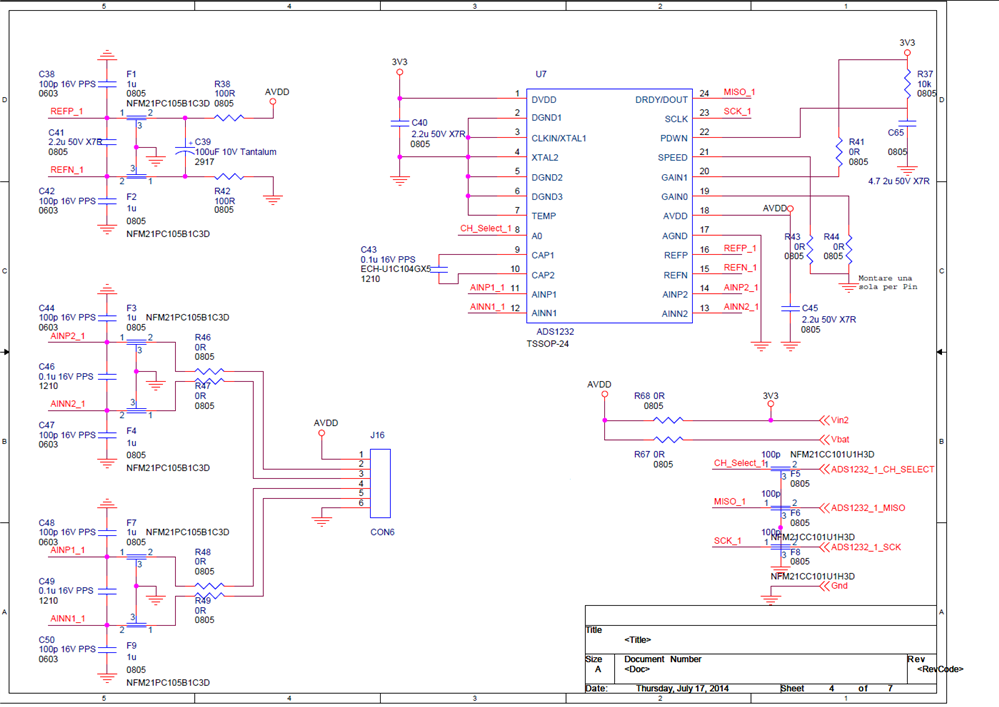
I've made a weight scale using the ADS1232 chipset connected to 4 strain gauges using a Wheatstone bridge configuration.

Everything seems ok, but after some day of operation, the ADS1232 outputs a pretty constant value (like -44) independently from the applied weight.

If I unpower and restart the system, it works correctly for 5-10 minutes before that the issue returns.

  • This's an example of the signal read from ADS1232 by SPI.

    The result is "right shifted" by 6 bits (assuming the 6 lower bits as noise)

    As you can see, the converter starts to output a constant value (15) despite the signal coming from the load-cell.

    000000000000000010100000    160    
    000000000000000010100000    160    
    000000000000000010100001    161    
    000000000000000010100001    161    
    000000000000000010100001    161    
    000000000000000010100001    161    
    000000000000000010100001    161    
    000000000000000010100001    161    
    000000000000000010100001    161    
    000000000000000010100010    162    
    000000000000000010100010    162    
    000000000000000000001111    15    <-- constant output begins
    000000000000000000001111    15    
    000000000000000000001111    15    
    000000000000000000001111    15    
    000000000000000000001111    15    
    000000000000000000001111    15    
    000000000000000000001111    15    
    000000000000000000001111    15    
    000000000000000000001111    15    
    000000000000000000001111    15    
    000000000000000000001111    15    
    000000000000000000001111    15    
    000000000000000000001111    15    
    000000000000000000001111    15    
    000000000000000000001111    15    
    000000000000000000001111    15    
    000000000000000000001111    15    
    000000000000000000001111    15    
    000000000000000000001111    15    
    000000000000000000001111    15    
    000000000000000000001111    15   


    Other informations are:

    AVDD = DVDD = 3.3V

    AGND = DGND

    AINP ~= AINN ~= 1.65V

  • Hi White Noise,

    Welcome to the forum! Regarding your schematic, I would remove the XTAL2 pin from ground and let it float.  I would also add some resistance to the analog input filters.  As to the data, it would be more helpful to see the raw data instead of the shifted data.  Sometimes it is easier to diagnose issues when all bits are visible.

    It is not clear if this pattern happens on just one input or both inputs.  Have you looked at both inputs to see if there might be a problem with just one of the inputs?

    Another question is you mentioned you have four load cells so how do you have the load cells connected in this circuit?

    Best regards,

    Bob B

  • Hi Bob,

    first of all thank you for your support.

    I'm using a single load-cell with 4 wire: sorry if I was not clear.

    I've removed XTAL2 pin from ground and I've replaced the 0 Ohms of AINP1 and AINP2 with 150 Ohm

    The voltage that arrives to AINP1 and AINP2 is 1.63V circa now.

    I've removed the shifted data.

    I've also put a 10n cap parallel to C45.

    Unfortunaly the problem is not solve.

    000000000010101011010001 10961

    000000000010101011001100 10956

    000000000010101011000111 10951

    000000000010101011000010 10946

    000000000010101011000010 10946

    000000000010101011000110 10950

    000000000010101010111111 10943

    000000000010101010111111 10943

    000000000010101010111010 10938

    000000000010101010110100 10932

    000000000010101010110111 10935

    000000000010101010111100 10940

    000000000010101010111110 10942

    000000000010101011000001 10945

    000000000010101010111011 10939

    000000000010101010111011 10939

    000000000010101010111101 10941

    000000000010101010111001 10937

    000000000010101010111100 10940

    000000000010101011000101 10949

    000000000010101010111111 10943

    000000000010101011000110 10950

    000000000010101011000111 10951

    000000000010101011000010 10946

    000000000010101011001011 10955

    000000000010101011000101 10949

    000000000010101011001000 10952

    111101111000000100001110 -556786    <-- ADS1232 starts with unsense data

    111100100110001000100101 -892379

    111100100111110001110001 -885647

    111100101001011001110101 -878987

    111100101011000011000010 -872254

    111100101100101010010000 -865648

    111100101110010001100001 -859039

    111100101111111001000001 -852415

    111100110001011111111111 -845825

    111100110011000111011111 -839201

    111100110100101101010011 -832685

    111100110110010010100100 -826204

    111100110111110111100010 -819742

    111100111001011101000100 -813244

    111100111011000010111000 -806728

    111100111100101000100011 -800221

    111100111110001011110010 -793870

    111100111111101111100011 -787485

    111101000001010010100001 -781151

    111101000010110101111011 -774789

    111101000100011001100100 -768412

    111101000101111100000101 -762107

    111101000111011110000110 -755834

    111101001000111111100001 -749599

    111101001010100001011100 -743332

    111101001100000011001000 -737080

    111101001101100100010000 -730864

  • Hi White Noise,

    You have a very slow ramp through POR, so one thing to consider is to adjust the time constant so that it is shorter.  You only need 10us after power up for a delay.  Other than that it is difficult to say what might be going on.  It is unusual to see that much shift in the opposite direction without having the input actually drift in the opposite direction as well.  This reminds me to tell you that when you make a shift in your data you must make sure that the sign of the data carries as well.  Maybe you were already doing that, but it is a common error.

    To eliminate the effect of the load cell, I would connect a voltage divider to the inputs to see if you see the same shift without the load cells attached.  You will see strange data if one of the inputs slides out of the common mode input range.  Load cells draw a significant current, and if you have a connection that is poor you may see a heating issue that is limiting current to the load cell and shifting the common mode or input level.

    Best regards,

    Bob B 

  • Hi Bob,
    do you think that a slow ramp through POR can cause some problem? I'll try to reduce that ramp.
    For what concerning the "negative right shift", my compiler preserves the sign-bit.

    I'll try to use a voltage divider (REF+ - 10k - AINP - AINN - 10k - REF-) to remove the cell as you suggested.
    I will keep you informed.

    Best regards,
  • Hi Bob,
    unfortunately I've done the new tests without any success.
    Now I'm using a trick:
    - power on ADS1232
    - do Offset Calibration
    - Acquire data for 15-20 seconds
    - power down ADS1232
    - and so on
    It's not a good and clear solution, but at the moment I'm not able to understand what's wrong.

    Regards

  • Hi White Noise,

    It appears that something is heating up and causing an issue.  Can you send me your layout and a picture of your test setup?

    Thanks,

    Bob B

  • Hi Bob,
    I'll send you the layout
    can you send me a private email address?
    Thank you

  • Hi White Noise,

    You can either connect to me on the forum directly by clicking on my name and starting a private conversation or you can reach me via email at:

    pa_deltasigma_apps@ti.com

    Best regards,

    Bob B