This thread has been locked.

If you have a related question, please click the "Ask a related question" button in the top right corner. The newly created question will be automatically linked to this question.

DAC6573 EVM

Other Parts Discussed in Thread: DAC6573

Hi all,

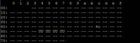
I am trying to interface a DAC6573 EVM with an MPU via I2C. The EVM is being used in default settings. I have used i2cdetect to confirm that the device is found and its address listed as 0x4C. The data sheet says the address should be 0x98, so it is clear that the address is being shifted to a 7 bit address.

I believe that the command signal should be 0x10 in order to update DAC A with the data. I am trying to send a digital signals to the device but I am not receiving any output.

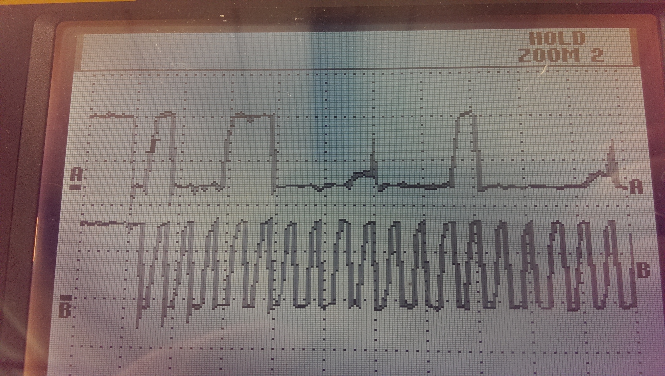
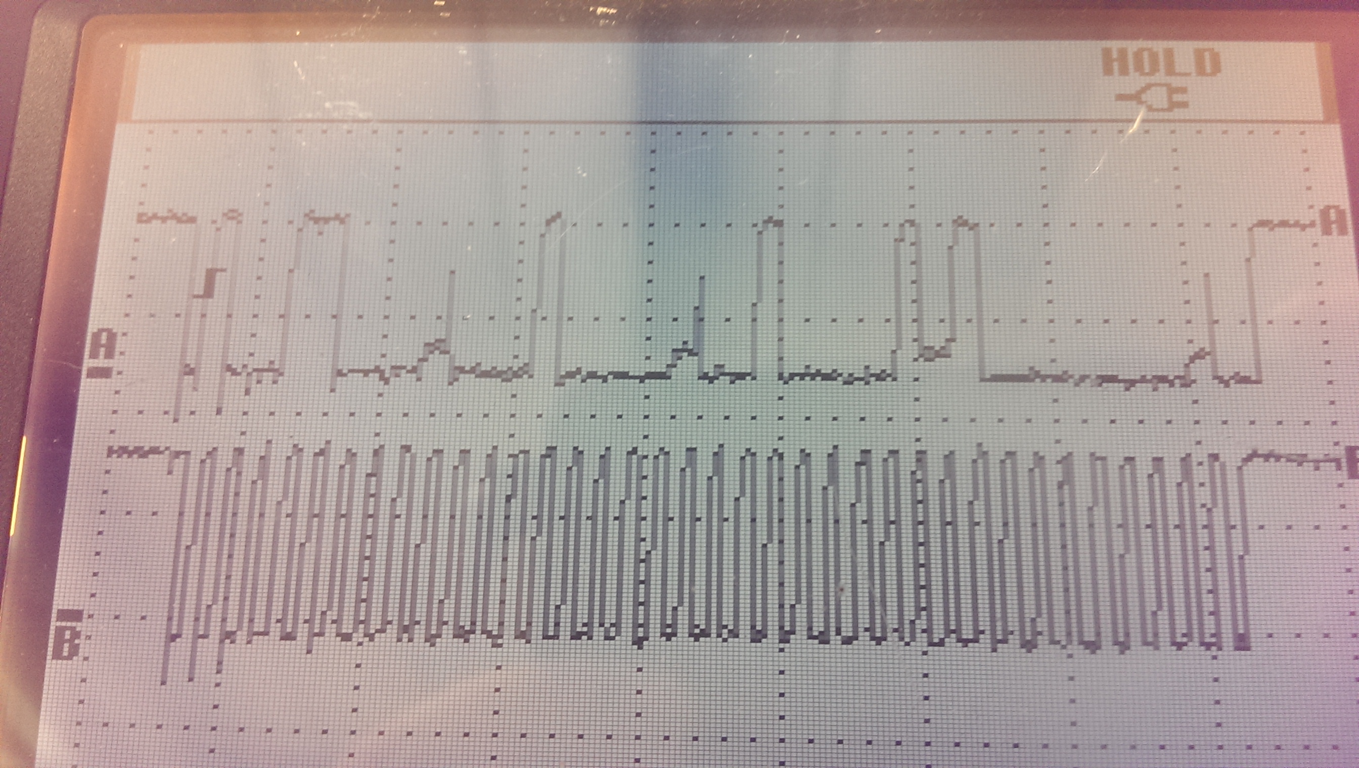
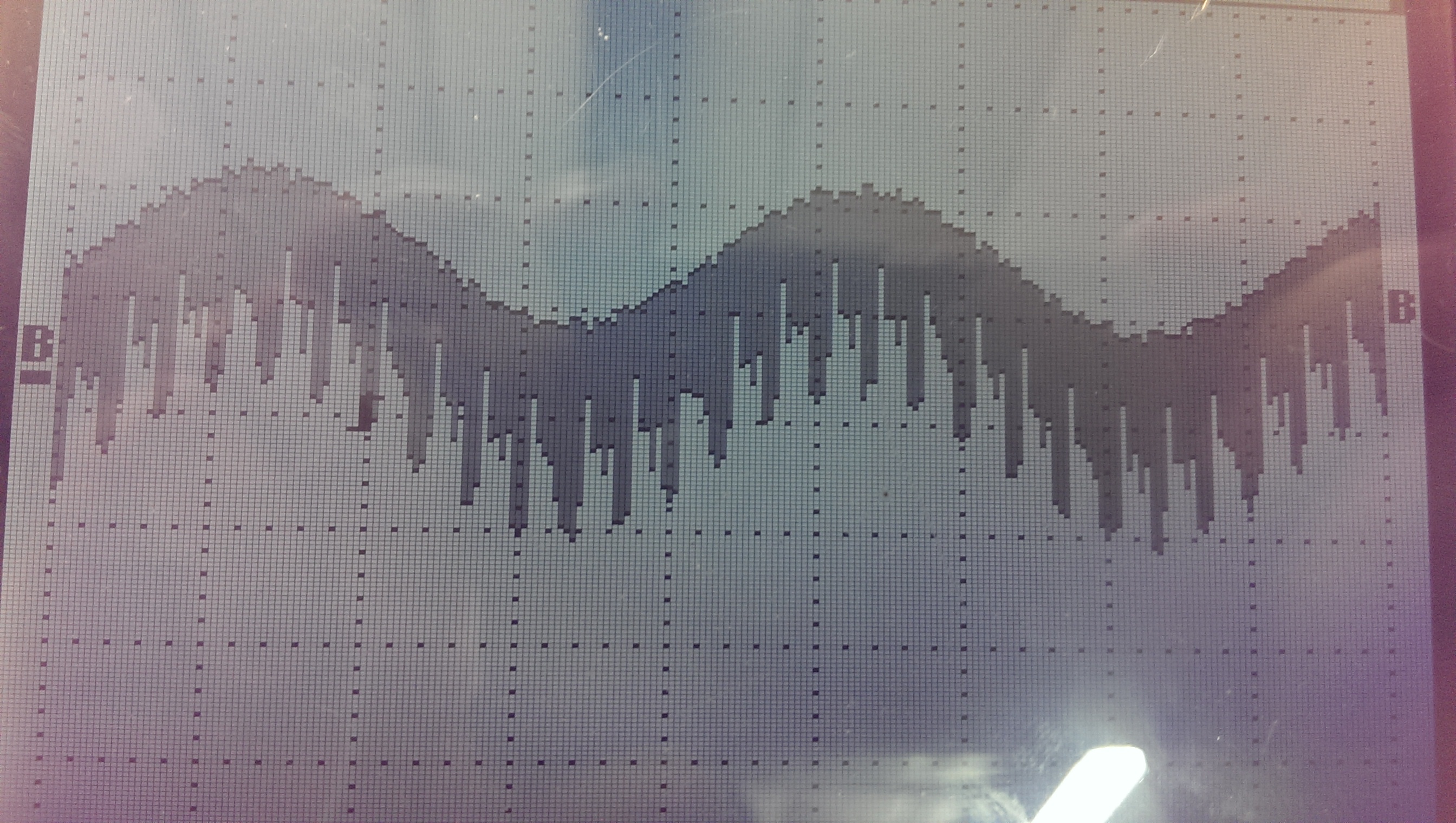
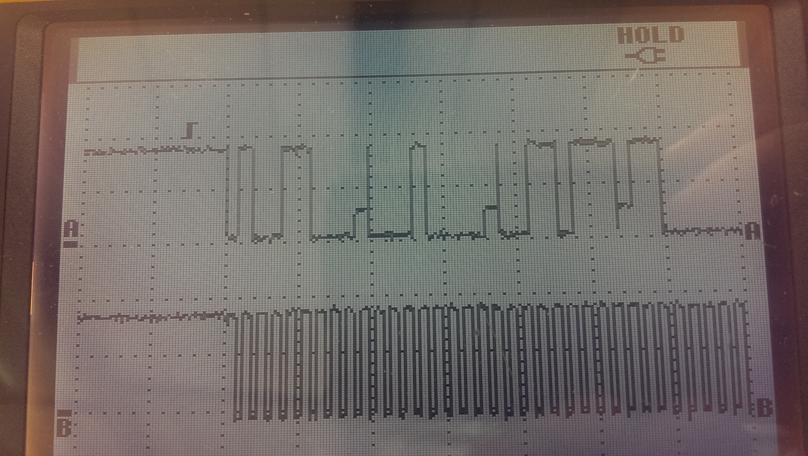
Below is an image of the SDA and SCL lines from the MPU. The data seems to be out putting 0x98 as the address, 0x10 as the command, then the MSB and LSB data. The only issue I see with the data is that the acknowledge bit seems to come in between the rails. Otherwise, the data seems to be correct.

A is the SDA and B is the SCL for reference.

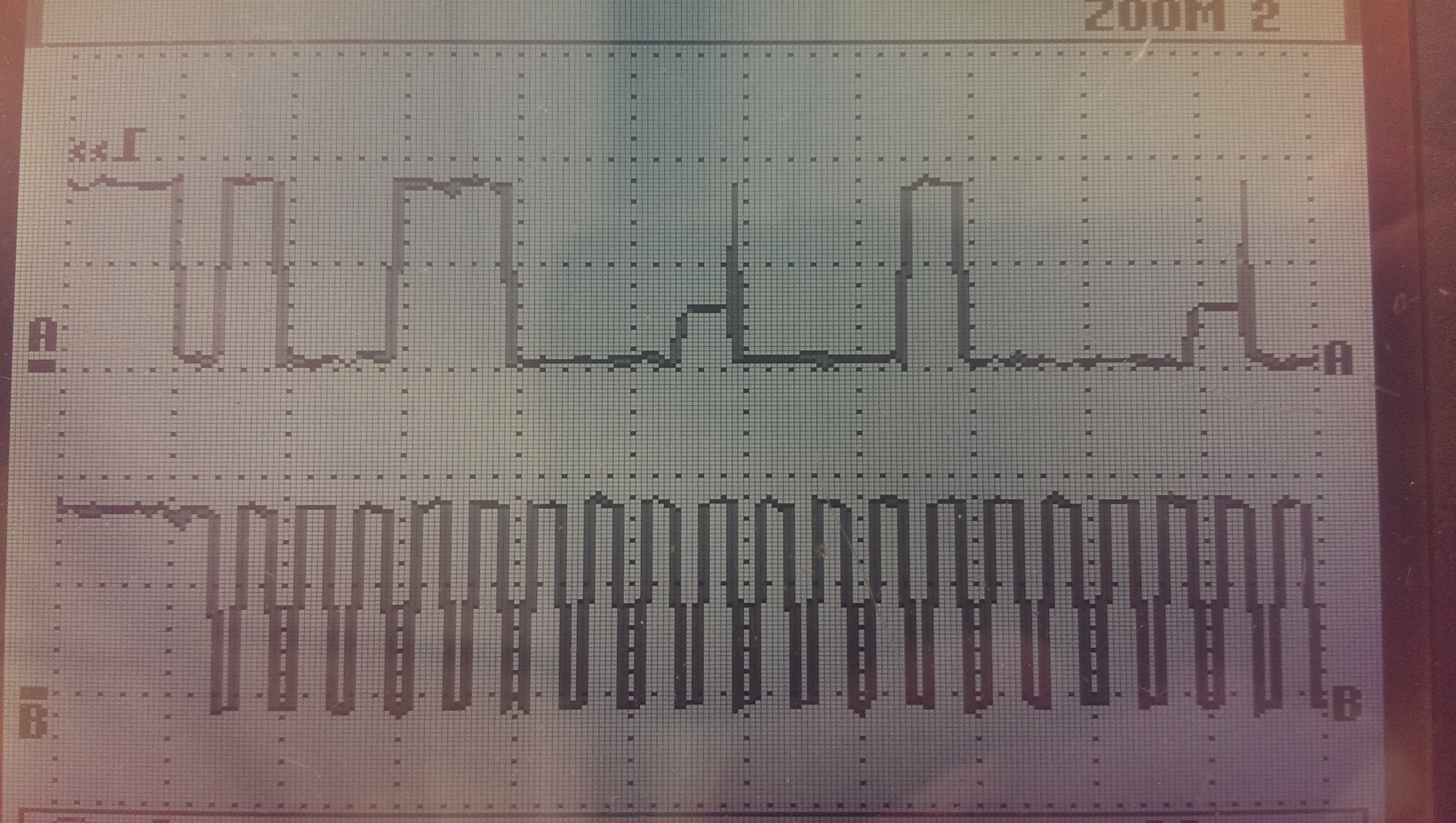
A more zoomed in image.

So I am unsure if there is an error with the i2c interface or where exactly the error could be.

Thank you for your time and consideration.

-Kyle

  • Hi Kyle,

    It seems that the master device is recognizing the ACKs. Can you try to take an oscilloscope plot directly at the device pin?

    The dirty ACKs in your board are definitely a concern. I have seen this type of behavior when having two different pull-up networks. Do you know if your master device provides it own pull-up resistors for the I2C interface? The DAC6573EVM also has a pull-up network so this may be causing the problems.

    A quick test to check if your master device does have a pull-up network would be to take an oscilloscope capture of the I2C lines without the DAC6573EVM. If the HIGH data bits look normal, then it means that your master devices does have a pull-up network. If they instead lag behind or remain LOW, then it doesn't have one.

    If you find out that your master does have a pull-up network, then I would suggest that you remove R5 and R7 from the DAC6558EVM and try communicating with the device once again.


    What bytes are you trying to send to the DAC?

    From my end it seems that you are trying to seed the following:

    • ADDR = 0x98
    • CNTL = 0x01
    • MSB  = 0x37
    • LSB  = 0xC0

    Kyle_Freng said:
    I believe that the command signal should be 0x10 in order to update DAC A with the data

    The command to update the DAC is indeed 0x10, but it seems that you are using the command 0x01 which is an update only command. This means that the DAC will ignore the  MSB and LSB bytes and update the DAC output with the contents that are already stored in it's register. This may be a byproduct of the dirty ACKs. Your data may have been shifter over. Can you verify that your device is trying to send CNTL = 0x10?

  • Hi Eugenio,

    I did confirm that my device has some pull-up resistors on the i2c interface. I took off the R5 and R7 resistors like you suggested and measured the  i2c signals directly at the device pins as well. Unfortunately, that did not seem to get rid of the dirty ACKs in my signal. Yet, somehow I was able to get an actual output out of the EVM, albeit a very noisy one.

    Below I have included the updated I2C pin images and then the output image. The output resembles a sine wave which is exactly what I expect, but I was wondering if there was any way to reduce the noise on the output of the EVM or if I need to filter it out afterwards.

    Zoomed in Image of the I2C signals

    Original Signal

    Output

    Thanks,

    Kyle

  • Update:

    The noise was coming from the scope probe. Replaced the probe and the signals looked much better!

    Thanks Eugenio!
  • It's great to hear that there is progress on the debugging. Were you able to get the correct DAC output when using CTRL = 0x10?
    I can't see the scale in the plots that you shared.
  • Yes I was. The DAC was setup for an output gain of 2, my reference voltage was 2.5 V, and the output is a 0 - 5 V sine wave as expected.