This thread has been locked.

If you have a related question, please click the "Ask a related question" button in the top right corner. The newly created question will be automatically linked to this question.

ADS1120 MUX the switching timing

Other Parts Discussed in Thread: ADS1120

Hi,

My customer is facing the memory effect.

Could you tell me following thing to solve it?

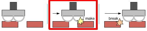
Which is the switch timing of MUX for ADS1120, "break before make" or"make before break"?

If it is "make before break", how long is channels connected?

Thanks and Regards,

Kuramochi


  • Hi Kuramochi-san,

    To help you with this problem I really need to know a lot more detail.  I need to know:

    • All register settings used (which will tell me PGA settings, data rate, mode of operation, etc.)
    • Power supply voltages and reference voltage source/voltage
    • Input voltages
    • Method of collecting data (polling DRDY or interrupt driven system)
    • Also a schematic and board layout would be helpful to see if there is a potential for analog crosstalk

    What happens on a mux change is the register value is decoded and the mux disconnects from the previous input channels then connects to the new channels.  Also, the digital filter is reset which actually starts a new conversion once the channels have switched.

    What sometimes happens when using continuous conversion mode is the previous channel data has not been read out at the correct time.  The best method is to use an interrupt driven system where the data is read immediately after the falling edge of DRDY.  Then you can change the mux right after the data has been read.  At this point the next falling edge of DRDY should be the new mux position data.

    If the interrupt method cannot be used, it is better to use the single-shot method where the conversion completes and then stops.  The data will never overlap in the START/STOP case.

    Best regards,

    Bob B

  • Hi Bob-san,

    Thank you for your comment.

    The mux changing of MUX for ADS1120 is "break before make", isn't it?

    The following are conditions;

    - Gain ⇒ ChA(IN0-IN1,differential):×1, ChB(IN2-IN3,defferential):×64

    - Data Rate ⇒ 2000sps

    - Mode ⇒ Single-shot method

    - Power Supply ⇒ AVDD:4V, DVDD:3.3V

    - Reference voltage ⇒ REFN0:AGND, REFP0:4V

    Could you tell me your address for sending the schematic?

    Thanks and Regards,

    Kuramochi

  • Hi Kuramochi-san,

    Yes the mux is break before make.  This is a very fast process, so I doubt that the issue is directly related to the mux.  Based on your settings, I think that the PGA may be in an overloaded state.  This can happen if the PGA is still at a gain of 64 when you switch from ChB to CHA.  In theory, the switch of both the mux and the PGA should happen within a couple nanoseconds of each other and this should not cause an overload.

    Can you tell me more about the process as to how the code is written to switch channels and start conversion?  Does the START/SYNC command get issued immediately after the register write?  Can you give the data results?  Can you send me scope shots of the communication?

    You can send schematics to pa_deltasigma_apps@ti.com .

    Best regards,

    Bob B

  • Bob-san,

    Thank you for your help.

    >how the code is written to switch channels and start conversion?
    Please refer following.
    -------------------------------------
     function1
     void ADCWriteByte(uint8 write)
     {
    U0CSR &= ~0x02; // Clear TX_BYTE
    U0DBUF = write;
    while (!(U0CSR & 0x02)); // Wait for TX_BYTE to be set
     }

     function2
    void ADCstart(void)
    {
    CS = CS_ENABLED;
    ADCWriteByte(ADC_START_SYNC);
    WAIT_US(2);
    //CS = CS_DISABLED;
    }

    code
    ADCWriteByte(0x40);
    ADCWriteByte( ADC_MUX_1_0 | GAIN11 ); ←This is repeating operation by 2 arguments
    ADCstart();
    -------------------------------------

    >Can you send me scope shots of the communication?

    What should we aim to get scope shots?

    Thanks and Regards,
    Kuramochi
  • Hi Kuramochi-san,

    The code flow appears to be ok, but I really don't know what is being sent.  I do not know what is on the inputs, and I do not know the register settings.

    When the PGA = 1 setting, is the PGA enabled or is it bypassed?

    Sending me the schematic would be helpful and the scope/logic analyzer shots would be helpful to see all timing of the communication.  I need to see all SPI signals.

    Best regards,

    Bob B