


Other Parts Discussed in Thread: ADS1299
Hello everyone,
I posted some problems about reading the registers of the ADS1299 EVM, but I didn't get an answer, so I'll post it again adding some more information and activities that I did after.
I installed the latest software (ads1299-eeg-fe-1.0.2) correctly on Windows 8, rebooting the machine with Signed Driver Enforcement disabled. The drives of module are also installed correctly, the device manager recognizes it as MMB0 (NI-VISA).
When I run the software, it shows "Connected to EVM", after that, it starts to reading registers (this takes a while), then it shows "Sync Complete...Ready"
Everything seems to be ok until now, but when I click on "Register Map sub-tab" on "ADC Register tab", All registers (including ID Reg) have a 00 HEX Value, and when I manipulate an ADS1299's configuration like a GPIO or enabling SBR1, nothing seems to change, and "Register Map sub-tab" does not update when I click on "Refresh registers".
Another issue that I found, is that when I click on Acquire or Continuous buttons, the screen "freezes" in gray and shows a pop-up with an error message, and then I can't do anything.
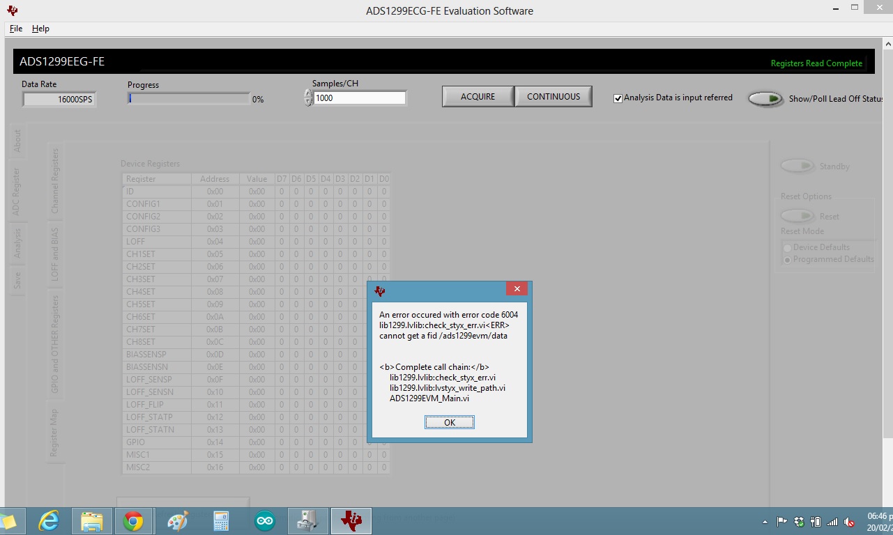
I tried to test the EVM on another machine with Win 7, but it's the same thing, then I tried to test it with a Win XP machine but I couldn't install the divers, the installation wizard shows an error with mmb0_visa.inf file.
The jumpers of the board has the default configuration. MMB0 is Rev D.
Yesterday I decided to test the daughter card (Rev B) using an Arduino UNO with the code below:
#include <SPI.h>
//SPI Command Definitions (pg. 35)
const byte WAKEUP = 0b00000010; // Wake-up from standby mode
const byte STANDBY = 0b00000100; // Enter Standby mode
const byte RESET = 0b00000110; // Reset the device
const byte START = 0b00001000; // Start and restart (synchronize) conversions
const byte STOP = 0b00001010; // Stop conversion
const byte RDATAC = 0b00010000; // Enable Read Data Continuous mode (default mode at power-up)
const byte SDATAC = 0b00010001; // Stop Read Data Continuous mode
const byte RDATA = 0b00010010; // Read data by command; supports multiple read back
//Register Read Commands
const byte RREG = 0b00000000;
const byte WRET = 0b00000000;
// pins used for the connection with the sensor
// the other you need are controlled by the SPI library):
//Arduino Uno - Pin Assignments; Need to use ICSP for later AVR boards
// SCK = 13
// MISO [DOUT] = 12
// MOSI [DIN] = 11
const int CS = 10; //chip select pin
const int DRDY = 9; //data ready pin
const float tCLK = 0.000666;
boolean deviceIDReturned = false;
void setup() {
Serial.begin(9600);
// start the SPI library:
SPI.begin();
SPI.setClockDivider(SPI_CLOCK_DIV16); //Divides 16MHz clock by 16 to set CLK speed to 1MHz
SPI.setDataMode(SPI_MODE1); //clock polarity = 0; clock phase = 1 (pg. 8)
SPI.setBitOrder(MSBFIRST); //data format is MSB (pg. 25)
// initalize the data ready and chip select pins:
pinMode(DRDY, INPUT);
pinMode(CS, OUTPUT);
delay(10); //delay to ensure connection
digitalWrite(CS, LOW); //Low to communicated
SPI.transfer(RESET);
digitalWrite(CS, HIGH); //Low to communicated
//Set up ADS1299 to communicate
// digitalWrite(CS, LOW); //Low to communicated
//// SPI.transfer(START);
// digitalWrite(CS, HIGH); //Low to communicated
delay(10); //delay to ensure connection
}
void loop(){
//Serial.println("Time: "+ millis());
if(deviceIDReturned == false){
getDeviceID();
deviceIDReturned = true;
}
}
void getDeviceID(){
// SPI.transfer(START);
digitalWrite(CS, LOW); //Low to communicated
SPI.transfer(SDATAC);
SPI.transfer(0x20); //RREG
SPI.transfer(0x00); //Asking for 1 byte (hopefully 0b???11110)
byte temp = SPI.transfer(0x00);
digitalWrite(CS, HIGH); //Low to communicated
Serial.println(temp, BIN);
}
The Arduino ADS1299 wiring shows below.

The jumpers configuration is like the default, except JP18, I uninstalled the jumper for using the internal clock.
I only got a 0 value on the serial viewer. Then I test it with another code.
#include <ADS1299.h> // I added the library successfully
ADS1299 ADS;
//Arduino Uno - Pin Assignments; Need to use ICSP for later AVR boards
// SCK = 13
// MISO [DOUT] = 12
// MOSI [DIN] = 11
// CS = 10;
// DRDY = 9;
// 0x## -> Arduino Hexadecimal Format
// 0b## -> Arduino Binary Format
boolean deviceIDReturned = false;
boolean startedLogging = false;
void setup() {
Serial.begin(115200);
Serial.println();
Serial.println("ADS1299-bridge has started!");
ADS.setup(9, 10); // (DRDY pin, CS pin);
delay(10); //delay to ensure connection
ADS.RESET();
}
void loop(){
if(deviceIDReturned == false){
ADS.getDeviceID(); //Funciton to return Device ID
//prints dashed line to separate serial print sections
Serial.println("----------------------------------------------");
//Read ADS1299 Register at address 0x00 (see Datasheet pg. 35 for more info on SPI commands)
ADS.RREG(0x00);
Serial.println("----------------------------------------------");
//PRINT ALL REGISTERS... Read 0x17 addresses starting from address 0x00 (these numbers can be replaced by binary or integer values)
ADS.RREG(0x00, 0x17);
Serial.println("----------------------------------------------");
//Write register command (see Datasheet pg. 38 for more info about WREG)
ADS.WREG(CONFIG1, 0b11010110);
Serial.println("----------------------------------------------");
//Repeat PRINT ALL REGISTERS to verify that WREG changed the CONFIG1 register
ADS.RREG(0x00, 0x17);
Serial.println("----------------------------------------------");
//Start data conversions command
ADS.START(); //must start before reading data continuous
deviceIDReturned = true;
}
//print data to the serial console for only the 1st 10seconds of
while(millis()<10000){
if(startedLogging == false){
Serial.print("Millis: "); //this is to see at what time the data starts printing to check for timing accuracy (default sample rate is 250 sample/second)
Serial.println(millis());
startedLogging = true;
}
//Print Read Data Continuous (RDATAC) to Ardiuno serial monitor...
//The timing of this method is not perfect yet. Some data is getting lost
//and I believe its due to the serial monitor taking too much time to print data and not being ready to recieve to packets
ADS.updateData();
}
}
And this is what I obtained

Only 0´s again.
So. Does the ADS1299 IC of the daughter card damaged? Am I doing something wrong?
Thanks in advance.

