This thread has been locked.

If you have a related question, please click the "Ask a related question" button in the top right corner. The newly created question will be automatically linked to this question.

Problems connecting INA333 with ADS1291/1298/1299

Other Parts Discussed in Thread: INA333, ADS1298, ADS1299, ADS1291, ADS1191

Hello,


I am trying to connect INA333 amplifier in front of the ADS to improve the signal gain. While I get a good ECG signal from the ADS itself, I am unable to obtain any signal (only noise) with INA in front. Can this amplifier be connected before the ADS for improving signal gain ? Is there an example schematic for this ? Also, how should the VREF of the INA be connected to ADS ?


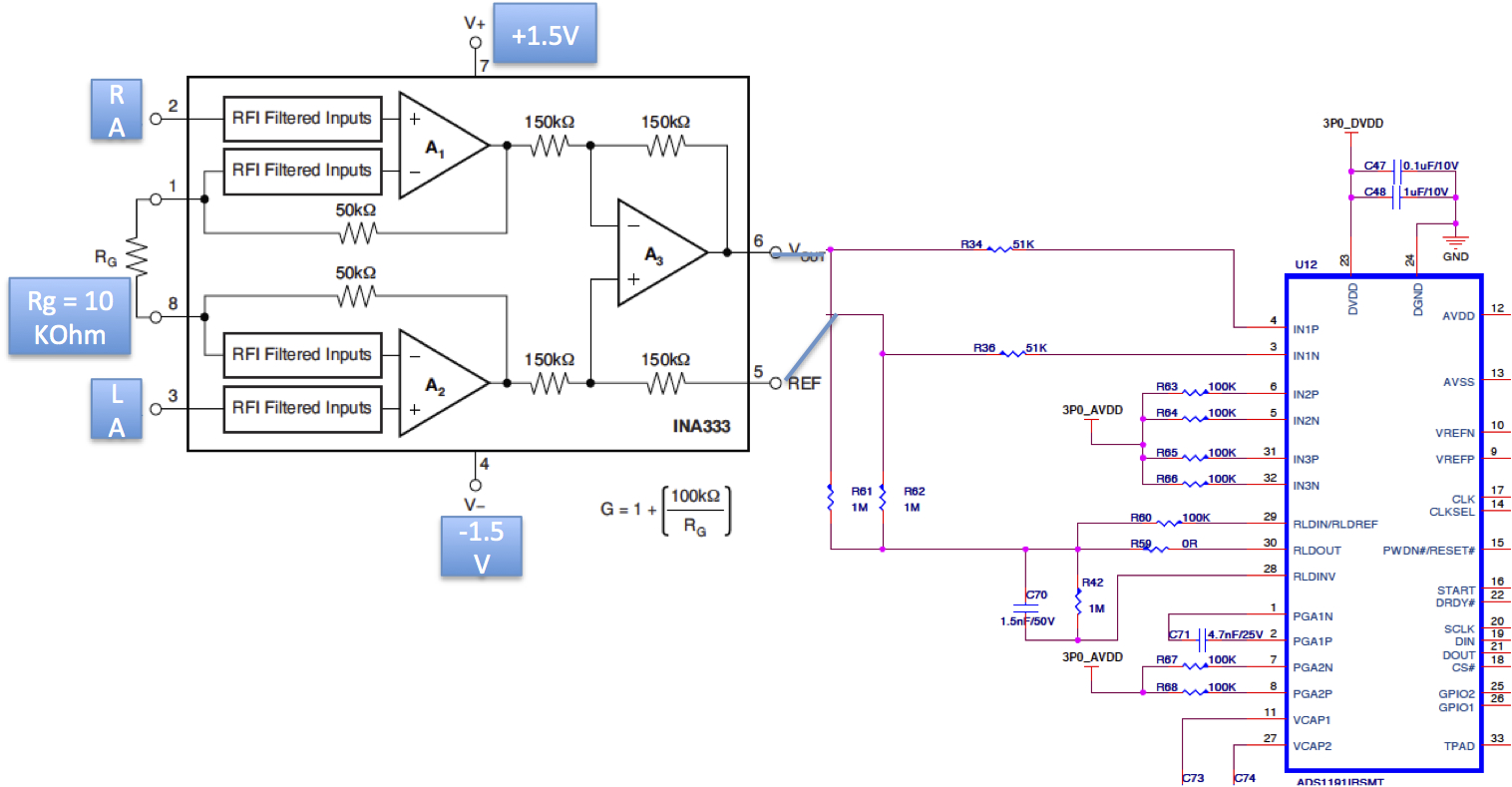
Here are the current settings for the INA: 2, 3 pins connected to RA and LA of body, 1,8 pins: 10 Kohm resistor (for gain of 11), pin 7: +1.5 V, pin 4: -1.5V, pin 5 (VREF): connected to ground. The output from INA is taken from pin 6 and the VREF (pin 5) and are fed to the ADS (similar to feeding RA and LA to ADS).

regards,

  • Hi James,

    What gain are you trying to achieve? All of the ADCs you mentioned have internal programmable gain amplifiers. The ADS1291 and ADS1298 have selectable gains up to 12 and the ADS1299 has a gain of up to 24. If you need more gain than the ADCs themselves can provide then I'd love to help you use the amplifier you've chosen or perhaps find a different device that might suit your needs better.

    Regards,
    Brian
  • Hi Brian,

    Thanks for the reply! Indeed for my application I require 50x to 100x more gain than the 12x or 24x from ADS chips. With the above configuration of INA333, I manage to get a signal if I touch the ground of the power supply by hand (any contact with body), and when removing the VREF to ground connection. Would be great to get your feedback on the choice of amplifier/device.

    regards,
  • James,

    Would you mind attaching a schematic of your setup?

    Brian
  • Here is the schematic (in this one, with ADS 1191, but similar set-ups were used for other ADS chips - 94/98/99 as well). The block on left is INA 333 and the outputs from it (pins 6 and 5) are connected to the IN1P and IN1N of the ADS 1191 chip.

  • James,

    What power supply values are you using for the ADS1191?

    Brian
  • Hi Brian,

    The supply voltage for ADS 1191 is 3.3 V, 0.6 amps.

    regards,
  • James,

    You said earlier that you get a signal if you remove the connection from the REF pin to ground. It seems from your schematic that the REF pin on the INA333 is connected directly to the IN1N pin of the ADS1191 without a ground connection. Is this the case where you receive a signal? Also, what is the negative supply voltage for the ADS1191? I'm assuming that when you said 3.3 V you meant unipolar 3.3V (AVDD = 3.3 V, AVSS = 0 V). For debug purposes, I would advise that you send a known signal through the INA333 and read the output without connecting the ADS1191 so you can ensure that device is functioning properly.

    Brian