This thread has been locked.

If you have a related question, please click the "Ask a related question" button in the top right corner. The newly created question will be automatically linked to this question.

AMC7812 DAC output problem

Other Parts Discussed in Thread: AMC7812, AMC7832, AMC7836

Dear,

We just designed a prototype card with AMC7812, the main purpose is to use DAC output, so far we can communicate by I2C to the card but we have problem with DAC output, it always show 0 volts, ths DAC latch are written correctly, because just reading afer writing give us the correct value, but the physical ouptut still 0 volts. in our design we just pointed a minor difference with the AMC7812 EVM design the capacitor connected to AGND and REF-OUT (56) and REF DAC (57) was missing in our design , does this non existing capacitor can affect the DAC output ?

Best Regards

Jean-Michel Escalon

  • Howdy Jean-Michel,

    Welcome to the e2e forums!  May I ask what the end application is, as it is always interesting to find out what our parts are being designed in.  

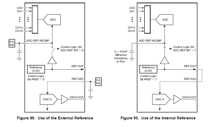
    The capacitor is generally recommended for additional noise filtering.  Are you using the internal reference? If so, there are a couple of registers you may need to set to fully activate the internal reference block.  You can do a quick check by measuring the voltage at REF-OUT.  If the voltage is not 2.5V, then the internal reference block is not enabled.

    When using the internal reference block, the PREF bit (bit 13 of 6Bh) should be set to '1', this activates the reference block which would then output the internal reference voltage to the REF-OUT pin.  The REF-OUT pin should connect to the REF-DAC pin as illustrated below.

    Best Regards,

    Matt

  • Dear Matt,

    First thank for your Ultra fast answer.

    We made more progress, in our design REF OUT and REF DAC are tied together, but was 0 volts on these line until we modfied register 0x6B with value 0X2000 (as you requested !), now we have 2.5 volts on the ref line wich is good, BUT still ave 0 volts on DAC output.

    In the Init sequence we do the following :

    register 0x6B value 0x0200
    register 0x4C value 0x2400
    register 0x59 value 0x0FFF

    is there any different sequence to do at the init ?

    After that we send value to DAC.

    Any idea ?

    regards
    Jean-michel
  • The sequence looks correct, there is just one register setting that you may be forgetting to set, but before I get to this I wanted to verify the following:

    register 0x59 value 0x0FFF

    The write above sets all DACs for a gain of 5XVref.  The default is 2xVref.

    The register 0x6B is also used to power all DACs, this information is found on page 80 of the DS.  For instance writing 0x3FFE to register 0x6B will activate all DACs with internal reference block.

    It should also be noted that this device has no required power sequence, but after entering power-up, a hardware reset is required to ensure specified device operation.  More information can be found in the Power-Supply Sequence section of the DS listed on page 49.

    Matt

  • Dear Matt,

    Yes the Gain of 5 is normal since we need 0-10 volts output, finally the solved solution comes from register 0x6B where we sent now 0x3FFE and the DAC works... great !! but some sample code will be welcome I think. We can continue our work, thanks alot.

    I forgot to tell that our application is something linked to Home Automation, AMC7812 was selected for his ability to have DAC, ADC and GPIO in same IC with I2C capabilities and the DAC 0-AVcc was key choise for us. The MUST of design will be th ability to have voltage divider in the ADC input ....

    Let now test ADC features.

    Best Regards
    Thanks
    Jean-Michel
  • Howdy Jean-Michel,

    That's great, I will update this post with some sample code later today.  The end application seems very interesting and thank you for your interest in the AMC7812 device.  

    Regarding the AMC7812 ADC inputs, the AMC7812 uses a SAR ADC architecture.  As such, it needs to be driven with a low impedance source in order to fully charge the internal sampling capacitor.  In applications where the source impedance is high a voltage follower or buffer can be used to condition the input before applying to the ADC inputs.  To get a better understanding of what the ADC equivalent circuit looks like please refer to the "ADC OVERVIEW" and "ANALOG INPUTS" section of the datasheet.

    Best Regards,

    Matthew Sauceda

  • Dear Matthew,

    The ADC part is now working after some trial, my main request was the fact that ADC input is only Vref or 2 x Vref, and with 2xVref you can not input 10 volts, you are oblige to divide before input, which is not always convenient especially if you have 10 channels ADC. since the AMC7812 has the capabilities to DAC 0 to 12 volts, why the ADC has not this features... it was just a dream..

    Best Regards

    JM

  • Howdy Jean-Michel,

    Yes you are correct that the acceptable ADC ranges for the AMC7812 device are seclectable between 0 to Vref, or 0 to 2xVref.  There are other AMC devices which include ADC input ranges of -12.5 to 12.5.  Such devices include the AMC7832 and AMC7836 device.  I would encourage you to take a quick peek at the datasheets, as these devices are also analog monitoring and control devices that house ADCs, DACs, and GPIO.

    Best Regards,

    Matt

  • Dear Matt,

    It is good to know about the other circuit but unfortunatly these are SPi only and not I2C, and I2C was one of the key choice.

    Best Regards

    JM

  • Hello Jean-Michel,

    I've included the register sequence for ADC configuration below:

    * 0x4C AMC Configuration 0 (Set ADC-REF-INT to '1')
    * 0x4D AMC Configuration 1 (Set Sampling rate)
    * 0x50 ADC Channel (Set channels (0-12) for single-ended or differential)
    * 0x51 ADC Channels (Set remaining channels (13-15) for single or diff)
    * 0x52 ADC Gain (Set Gain for channels)
    * 0x6B Power-Down Register (Set ADC and PREF bits to '1' to power Internal Reference and ADC Block)
    * 0x4C AMC Configuration 0 (Set for direct or auto mode)

    In direct mode an internal or external trigger is required for conversion. You can set the ICONV bit by writing to the AMC configuration 0 register or externally through the /CNVT input. In automode, once the ICONV bit is set the ADC will perform continuous conversions at the rate specified by the sampling rate set in the AMC Configuration 1 register.


    Best Regards,
    Matt

  • Dear Matt,

    Thanks a lot for this precious information , my register was good but not send in the right order. Another question concerning reset register, in DS it is written :

    Software Reset Register (Read/Write, Address = 7Ch, Default = NA)

    "The Software Reset Register resets all registers to default values, except for the DAC Data Register, DAC Latch,
    and DAC Clear Register. The software reset is similar to a hardware reset, which resets all registers including
    the DAC Data Register, DAC Latch, and DAC Clear Register. After a software reset, make sure that the DAC
    Data Register, DAC latch, and DAC Clear Register are set to the desired values before the DAC is powered on."

    it says reset all registers to default EXCEPT DAC register... and just after it is written which resets all registers including the DAC date register ... these sentences are correct ?

    For us it is little complicate since the DAC power I mean the 12 volts power is always ON, in that case does 7Ch function can be use or not ?

    best regards
    JM
  • Just as the text says, a software reset resets all registers to default value, with the exception of the DAC Data Register, DAC Latch, and DAC Clear Register.

    A hardware reset resets all registers to default value. 

    In both cases the powerdown register (0x6B) gets reset to default, so must be set to turn on desired DACs, as well as Internal Reference Block.

    The datasheet just notes that, in the case of a software of hardware reset, make sure the values listed in the DAC Data Register are the ones you wish to use before turning on the DACs via the powerdown register.

    Best Regards,

    Matt