Hi,
I have the ADC1xDxxxx(RF)RB board configured for the ADC12D1600 (our target part for our design).
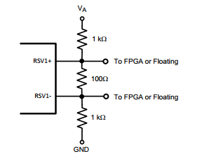
The schematic shows that on each of the 4 output data buses, there are two sets of three resistors each, going from V_ADC to ground. It's not clear what they hook up to but based on the table, they appear to be LVDS signal terminations in case a 10-bit device is used. For 12-bit devices, the table specifies "NA".
But looking at the board, it looks like the resistors are populated. Was that an oops? Or is there something that we need to consider in our board design since, based on the data sheet, it looks like all of the drivers are the same.
Thanks,
rich :-)