This thread has been locked.

If you have a related question, please click the "Ask a related question" button in the top right corner. The newly created question will be automatically linked to this question.

ADS1120 Problems with External Reference and reading unlinear

Other Parts Discussed in Thread: ADS1120, ADS1220, MSP430F135, MSP430F5510, ADCPRO

Hi.

Using the ADS1120 to measure 4 single ended inputs.


I am using an external 1.25V reference.

The code i'm using is based on the example RTD Temp Transmitter using the ADS1220.

I'm bit bashing the SPI connection, and at the moment I'm running it very slowly.


My config is

void ADS1120_setup(unsigned char inputMux)
    {
        unsigned char config[4];
        config[0] = inputMux | ADS1120_GAIN_1 | ADS1120_PGA_BYPASS;
        config[1] = ADS1120_DATA_RATE_20SPS | ADS1120_OP_MODE_NORMAL | ADS1120_CONVERSION_SINGLE_SHOT | ADS1120_TEMP_SENSOR_OFF | ADS1120_BURN_OUT_CURRENT_OFF;
        config[2] =  ADS1120_VREF_EXT_REF0_PINS | ADS1120_FIR_50_60 | ADS1120_LOW_SIDE_POWER_OPEN | ADS1120_IDAC_CURRENT_OFF;
        config[3] = ADS1120_IDAC1_DISABLED | ADS1120_IDAC2_DISABLED | ADS1120_DRDY_ON_DOUT_DRDY;
        ADS1120_Write_Regs (config, ADS1120_CONFIG_0_REG, 4);
        return;
}

The first problem, if I set config register 2 to External Reference REFP0 and REFN0 (see above), The counts do not change with input, seems to sit at a few hundred counts.

If I select internal reference, the counts change (more like I expect), but I don't get a 2.5V FS, it is scaled to 1.25V.

One of the inputs has a pot down, R1 = 400k, R2 = 50k.

So 10V input = 1.111V   (my reference should be 1.25V)

I have a mV source connected to the pot down. I've calibrated the adc output into voltage, calibrating it at 2 and 8V dc.

The signal becomes un-linear  at  (approx)  0.7V ( 0.07V after pot down) and 8.6V (0.95555)

I originally tested my circuit connected to the ADS1120 Dev board before layout my PCB, and everything worked great.

Any idea's what i'm doing wrong.

Regards

Nick Price

  • Just to confirm.
    I have the PGA turned off,
    Gain = 1
    No IDAC
    20 SPS
    50 and 60Hz filter on
  • Hi Nick,

    your schematic shows that you connected the reference voltage to the negative reference input?!? If that is the case, then your system will not work.
    Also, when using the internal 2.048V reference you will not be able to measure signals that are larger than 2.048V when using a Gain=1.

    Regards,
  • Wow, you are correct. I can't believe I missed that one, D'oh


    A little cutting and strapping required.


    It still doesn't explain why the reading in unlinear on the 2.5V internal reference.

    But will come back after changing around the reference. :)

    Thank you.

  • Hi Nick,

    don't worry, those things simply happen.

    I agree, this will not explain the nonlinear behavior when using the internal reference. One thing you should make sure is that in your code you use a reference voltage of 2.048V when using the internal reference (instead of 2.5V).
    Did you try to connect a voltage source to one of the inputs to see if you can measure that correctly?

    Regards,

  • Yes, un-linear on external and internal references.


    I replace chip today, as maybe somehow I've damaged the chip.

    I have 4 analogue circuits feeding in the the ADC, and all channels are un-linear.


    The sources have all been calibrated against a 6.5 digit meter.....


    Will comeback later with my progress.

    Nick

  • All fixed, replaced the ADS1120 all working now.

    one of the inputs is ratiometric, I have a 10k 0.1% between input and +Vref, and put a 10k 0.1% between input and Avss.

    One problem chip read 32692 counts, replacement reads 32678. I'm done a lot of modification to the board, and I guess at some point the chip was over stressed.

    Regards

    Nick
  • Hi Nick,

    thanks for the update. I am glad you got your system working now. Let us know in case you run into any other issues.

    Regards,

  • Hi Joachim
    My ADS1120 has become un-linear again. It worked fine for a few hours, I'm wondering if this chip is very sensitive to ESD discharge. Would ESD damage cause un-linearity?

    Unfortunately I recently moved office, and my new carpet causes me to charge up something terrible.

    I will scope the circuit to see if i have any strange oscillations going on...

    Any ideas welcome

    Nick
  • Hi Nick,

    You may want to consider the large resistances you are using in relation to the lower switched cap impedance with the PGA bypassed.  The switched capacitor input can appear non-linear near analog ground if insufficient charge is available to charge the input caps.

    Best regards,

    Bob B

  • I replaced the ADS1120 this morning, and everything was fine. With the 10k || 10k across Vref (1.25V external) to Avss, it was measuring 32678 counts. Resistors are 10k 0.1%.

    After a few hours of playing around on the inputs it not linear again, now measuring 32508 (260 counts low). I work that out as 150 ohms out.

    The analogue input stage I've used for over 6 years on a MSP430F135 using the internal 12bit ADC. But now I've chosen to use the MSP430F5510 and the ADS1120.

    I will replace the chip again, and make sure my wrist strap stays on.

    I understand the linearity will not be so good below 0.1V, this isn't an issue, as most of my input are offset from 0V. But being un-linear in the middle of the range isn't good.

    Nick
  • Hi Nick,

    What is the input voltage you are applying? And is it referenced to analog ground?  Also, you are not actually measuring the 'middle of the range' as the codes you are seeing are near positive full-scale.  The ADS1120 will only measure differentially, so with a single-ended measurement you will only have 2^15 measureable codes (from 0 to 0x7FFF). Codes from 0x8000 to 0xFFFF are negative codes where AINP is more negative than AINN.  Negative full-scale would be AINP connected to 0V and AINN connected to 1.25V using 1.25V for a reference.  In no way should your inputs ever exceed 0.3V above AVDD or 0.3V below AVSS.

    Best regards,

    Bob B

  • I've taken another prototype board

    Added the 2's comp to the received data. and the values are changed from 32768 to 65535.

    But the values are still un-linear.


    At the moment I've got a 3wire resistance bridge , which I've checked the analogue voltage (the output is buffered) output below.

    The feeds into the ADC1120, on one of the four inputs.

    I'm using a 0.02% Tolerance resistance standard.

    counts at 100.00R  = 47898

    counts at 200.00R = 56618

    counts at 150.00R = 52008

    counts at 150R should be 52268

    Now taking into account voltage at 100R is 0.83151 and voltage at 200.00 is 0.42855. This is well away from the rails, and I would expect it to be very linear.

    I taken the same circuit and feed it into the ADS1120 Dev board about 4 months ago, and it worked great.  Obviously using your windows application to the read the ADS1120. So I guess it's a software issue. But I can't see what. I will have to trawl through the code I guess

    Regards

    Nick

    DVM Expected Calculated Error
    Volts Ohms Ohms Ohms
    1.23446 0.000 0.002 0.002
    1.23035 1.000 1.022 0.022
    1.21427 5.000 5.013 0.013
    1.19412 10.000 10.013 0.013
    1.15386 20.000 20.004 0.004
    1.03297 50.000 50.005 0.005
    0.83151 100.000 100.000 0.000
    0.79118 110.000 110.008 0.008
    0.75090 120.000 120.004 0.004
    0.67634 138.510 138.508 -0.002
    0.63002 150.000 150.002 0.002
    0.42855 200.000 200.000 0.000
    0.22704 250.000 250.007 0.007
    0.06584 290.000 290.011 0.011
    0.04570 295.000 295.009 0.009
    0.02578 300.000 299.953 -0.047
    0.02182 301.000 300.936 -0.064
    0.01794 302.000 301.898 -0.102
    0.00726 305.000 304.549 -0.451

  • Getting no where here,
    Reading back the config, Register 0 , bit 0. PGA bypass is being cleared after sending config with it set.
    My gain if set to 0, so it should stay set.

    I'm going to put the Logic Analyser on the ADS1120 Dev Board, and see what the SPI logic like on there, when It is working correctly, and work it backwards. I missing something somewhere.

    Nick
  • Hi Nick,

    If the reference is 1.25V, the full-scale range is +/- 1.25V. The easiest way to read in the codes is to read directly to a signed short integer value.  As the values from the ADS1120 are already in binary 2's complement, you are already in the correct format for a signed short integer in C. If you use a 32-bit signed integer, then you will need to sign extend the value so that it shows the correct number.

    From the previous data results it would be helpful to see the actual code results and not a conversion to ohms.  Based on the codes you are giving me for 100 and 200 ohms, I see values that are in the negative direction.  This means the assignment to AINP is lower in voltage than AINN.  Based on your description it appears that you are making a single-ended measurement (referenced to ground).  This should only show codes in the positive direction (0 to 32767).  You should never see codes in the negative direction with this type of measurement.

    As you have discovered that the PGA is enabled, this might account for the negative codes as the MUX connections may not be as you think.  If you send me your logic anaylzer shots I might be able to see an issue with your register writes.

    Best regards,

    Bob B


  • I've not wired my analogue section to the ADS1120 Dev Board, just three connections (signal , ground and 1.25V reference)

    works great, very stable and linear.

    The counts are as follows

    100.00 ohms = 21720

    150.00 ohms =16440

    200.00 ohms = 11159

    I've tried it with and without the PGA, and it makes very little difference to the measurement, even at the ends of the range (0 to 300 ohms).

    I will not put the logic analyser on, and check what the commands you are sending look like.

    Regards

    Nick

  • I've not, should read "I've now"
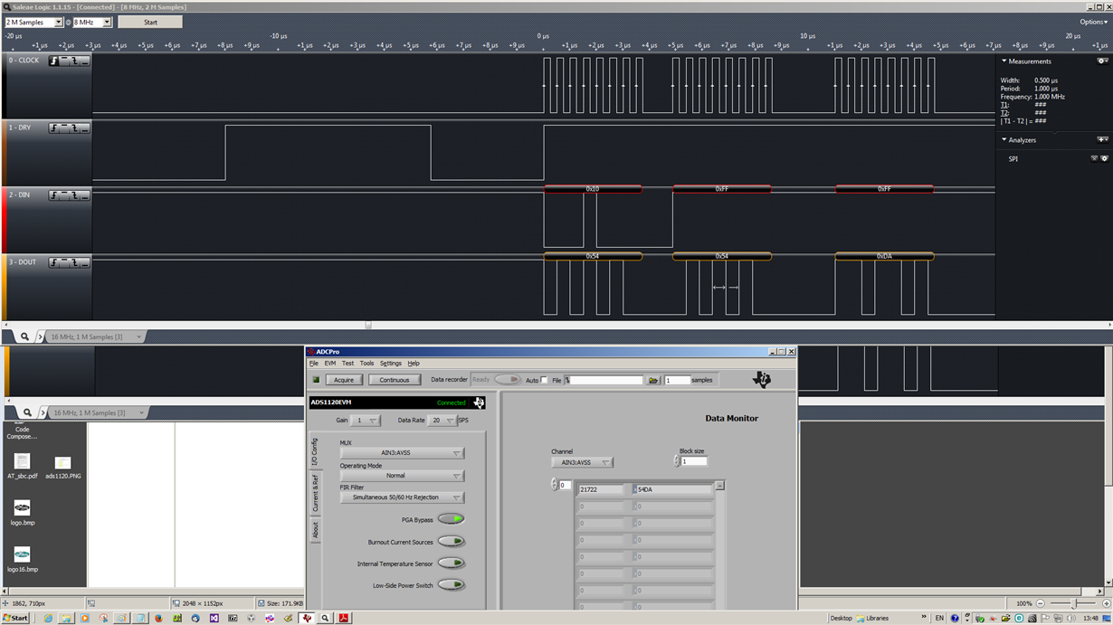
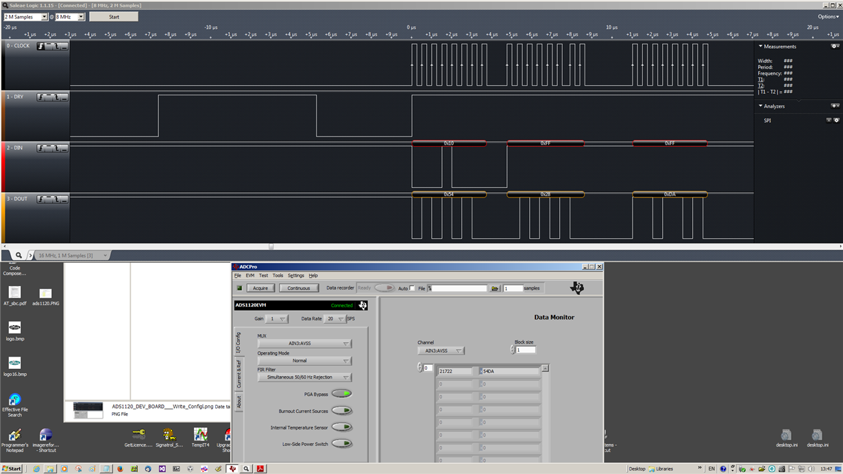
  • Ok, I've got the Logic Anaylser running, connected to the ADS1120 Dev board and runing ADCPro.

    Below is a capture when I click the acquire button on the ADCPro form.

    In the one image, ADCPro received 0x54DA, the logic analyser recorded  0x54, 0x54, 0xDA  (ignore the first byte because command was being sent)

    on the other image, ADCPro received 0x54DA, the logic analyser recorded 0x54, 0x28, 0xDA   ...
     don't under than this one.

    I can see the ADC is running in continuous mode.  I can also see your ADCPro software always gets the correct value. So what's the logic behind it.??

    Nick

  • Looks, like the above analyser problem was due to triggering for the data valid, should have been set to Falling Edge instead of Rising.
    I will not move back to my prototype and see if i get the same results.
    Nick
  • Hi Nick,

    Taking a single-ended measurement with the ADS1120, you will only see code values on the positive side unless there is a small negative offset on the device.  So you might see a negative code value near ground.  When looking at the code values returned from ADCPro, they do not match the code values you are seeing on your board.  ADCPro is showing only positive codes and the codes from your board are significantly in the negative direction.

    You need to double check the register settings and verify that you are setting the ADS1120 input mux to a single-ended channel.  Another thing to check is to make sure that you are not applying a negative voltage (referenced at ground) to the ADS1120 input.  You need to make sure that your voltage source and ADS1120 are at the same voltage ground reference.  The way to measure is to take your meter probe and connect the black (-) lead to the ground of the ADS1120, and with the red (+) probe connect to the analog input.  Maybe that is the way you are measuring your input voltage already, and if so you should focus on the register settings.

    Best regards,

    Bob B

  • I should ignore the codes from my board before. I put 2s comp on the data. Also there is a problem with the data coming back using my big bashing. I was out of the office yesterday, but back on it today.

    I make sure I reproduce the format from your ADCPro output/input.

    Unfortunately at this time I'm having serious problems with Code Composer 6, which intermittently will not debug the code. So it is taking a lot longer than expected to get this problem out of the way.
    Thanks

    nick
  • Still no progress due to GEL file error in Code Composer, can't get anything to running repeatedly. As soon as I make progress will come back to you.