This thread has been locked.

If you have a related question, please click the "Ask a related question" button in the top right corner. The newly created question will be automatically linked to this question.

ADS1256evm

Other Parts Discussed in Thread: ADS1256, OPA350

Hello,

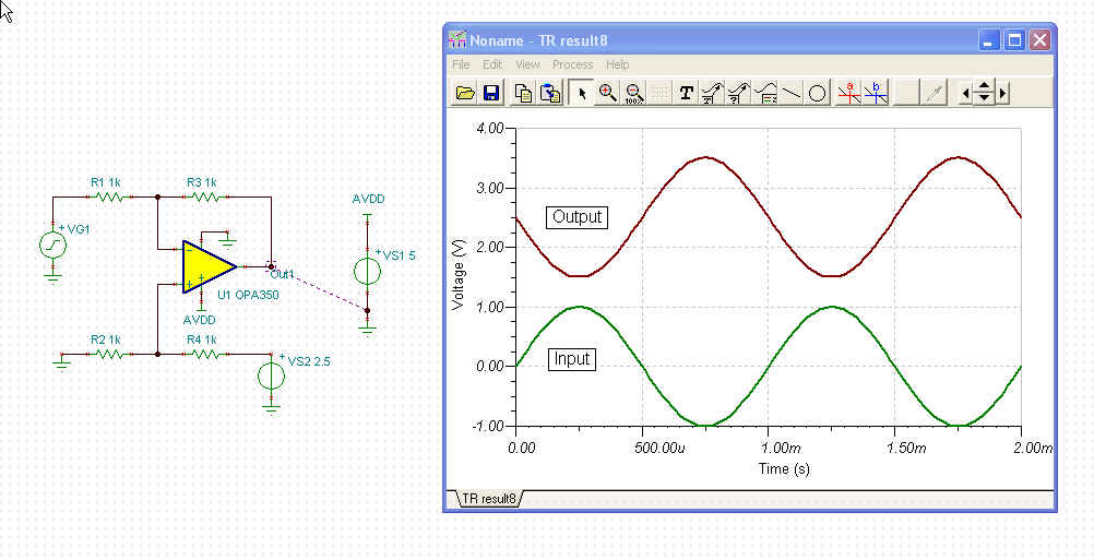
I must use the ads1256 evaluation module and I want to know if this module can accept negative voltage? (even if I think it can't) Because I have a analog input signal between -1V and 1V (sinus  curve centered in 0V). Do you know a method to translate this signal in the acceptable voltage range of the ads1256?


Thank you very much.


Remi Druel


  • If the ADS1256EVM is running on 0V - 5V supplies, then the input should not go outside this range.

    If you are starting with a sine wave input from +1V to -1V peak to peak, then you will have to shift the voltage up to the usable range.

    The attached schematic is capable of doing this with a single 5V supply. If you are using another amplifier, you'll have to consider the input common-mode range and the output range, as well as any other performance specifications that you are concerned about. There are also integrated difference amplifiers that can be used, but again you'll have to check the input and output ranges as well.


    Joseph Wu

  • Joseph,

    thank you for your schematic and your explanations, I thought to make a summing amplifier with an OPA but your solution seems to be better.

    if you supply the  opa350 with a single 0V - 5V supply, you can apply a negative signal on the input ??? Moreover, I saw in your "amplifer and data converter guide" that the input amplifier is generally connected to the ADC through an R-C network (p.57). This network actually serves as a “flywheel” in the presence of the current pulses created by the ADC’  input circuitry. Do you think I must add this network between the opa350 and the ads1256evm??


    best regards


    Remi Druel

  • Remi,

    Yes, the OPA350 operates from 0V - 5V as well, however with the resistor network and the 2.5V supply, it becomes a difference amplifier with the reference node at 2.5V. This will center the input common-mode voltage (as seen by the positive node of the OPA350) to 1.25V as the 2.5V supply is divided. If the input sine wave is between -1V and 1V, then you should be able to shift the voltage up. Note that for anything else, you'll just have to consider what your expected input to be and where you want the output to end up.

    When it comes to the R-C network, it may help, but is not a necessity. I wasn't sure where the this reference came from, but I finally found it in the Amplifier and Data Converter Guide. If you have it, the most important part is the capacitor. It acts as a charge bucket from which the ADS1256's sampling capacitors can draw from.  On the datasheet, there is some guidance to size of the network on page 28 in Figure 25. Also, there are capacitors on the inputs to the EVM. I would say the capacitors on the EVM are sufficient, and you might need some small series resistance to complete the network.

    Joseph Wu