This thread has been locked.

If you have a related question, please click the "Ask a related question" button in the top right corner. The newly created question will be automatically linked to this question.

Can ADS1x98ECG FE used for phonocardiogram?

Other Parts Discussed in Thread: ADS1198, ADS1298, ADS1298R

Hi! I'm new here, and I get a ADS1x98ECG FE.

I'ld like to try phonocardiogram monitoring. Can I use a sensor to connect to the FE and measure phonocardiogram?

Will there be any filter or amplifer which frequency response attenuates below 1kHz? Which channel is better for PCG useage?

Thanks for your kind response!

  • Hi Wendi,

    Welcome to the forum! The ADS1x98ECG FE is built for biopotential measurements and there is no built in functionality which supports the measurement of a phonocardiogram. That being said, there’s nothing to say that it isn’t possible to connect your own hardware that collects and conditions sound signals and sends it to one of the channels on the ADC. As long as your signal is filtered and amplified correctly and as long as you recognize that the highest sampling rates for the ADS1298 and ADS1198 are 32 kSPS and 8 kSPS, respectively, then it’s possible to build such a system.

    There is no high-pass filter on the ADS1x98ECG FE. The device is flexible in terms of channel configuration so you can configure the analog multiplexer on the device to send the inputs to any channel which isn’t already being used to measure something else. On the ADS1298R, the only channel which may be used for respiration measurement is channel one, so if you’re using the respiration circuitry, you cannot use that channel for anything else.

    In addition, there is no support on the EVM software for phonocardiogram measurements specifically, but the software is capable of outputting conversion data to a file which you or some software you create may analyze.

    Regards,

    Brian Pisani

  • Hi Brian,
    Thanks for your useful help!

  • Wendi,

    Let me know if you are able to get a system like that working!

    Brian
  • Hi Brian,

    I'v tried for PCG usage. I removed the jumpers and connect the microphone to one of the input channel. And it works.

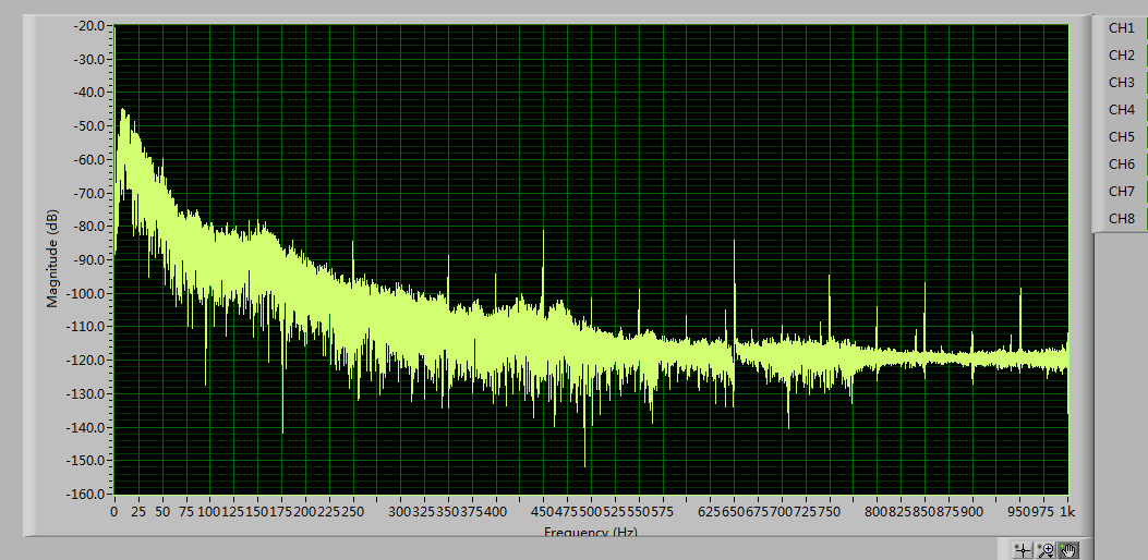
    The results looked great for PCG, but not well for smaller signal. I've found the power interface matters a lot. The spurs in frequency spectrum sometimes up to -50 dB, while the signal is always on that lever. Is there any way to improve?

    BTW, is the dimension for the frequency spectrum dBV? I've tried to get spectrum using voltage values download form the tool, and found the fft results calculated by MATLAB difference from the tool gives. Could you please tell me why?

    Thanks for your kind help.

  • Hi Wendi,

    I'm not sure I understand your first question. Are you saying the power supply noise (50/60 Hz) jumps to -50 dB? To improve your dynamic range, you could always use the internal PGAs to increase the amplitude of your signal before sampling.

    The EVM software gives the spectrum with decibels as its vertical axis with full-scale as its 0 dB point. To do something similar vector in MATLAB, you can make a vector like this: dataDB = 2*log10(output_voltage/reference_voltage);

    Regards,
    Brian PIsani
  • Hi Brian,

    Thanks for your reply.

    I hope to decrease the power supply noise. 

    Now, my signal looks like follows. And the power supply noise lead to spurs at 50Hz, 100Hz, 250Hz and so on, while some of my signal has the smaller level compared to the spurs. 

    Is there anything I can do to decrease the power supply noise?

    And for the spectrum, thanks for telling me the function. It helps a lot.

  • Hey Wendi,

    The appearance of power supply noise artifacts at the harmonics of the utility frequency will depend on your signal source. There are a few strategies that you could use to limit the strength of those signals both digitally and in analog. First, you can attenuate higher frequencies in analog by decreasing the cutoff frequency of your anti-aliasing filter. The cutoff frequency of the RC components on all of the inputs that the EVM ships with are already pretty low, so I'm not sure you'd want to decrease that lest you attenuate your signal frequency. One strategy you may want to implement if you spin your own board would be to pick an analog filter with a steeper response than the single pole RC filter that is on the EVM to more effectively attenuate those high frequency noise sourced before they get to the ADC.

    A strategy that may be implemented digitally in an application would be to pass the data through a real-time digital low pass filter on your host processor to eliminate the in-band high frequency harmonics. To attenuate the amplitude right at the utility frequency, you could also pass the data through a notch filter that you develop. If you'd like to evaluate such an option in MATLAB, you can build your filters there and pass the data you've already collected through them to see how the response looks.

    Regards,
    Brian Pisani
  • Hi Brian!
    Thanks for your reply! It helps a lot!
    I've tried the digital ways and they worked good. I'll try to implement the analog way for my own board.