


Hi
We use AMC1305 as a current sensing by the circuit from tidu499a (http://www.ti.com/lit/ug/tidu499a/tidu499a.pdf) Figure 21.

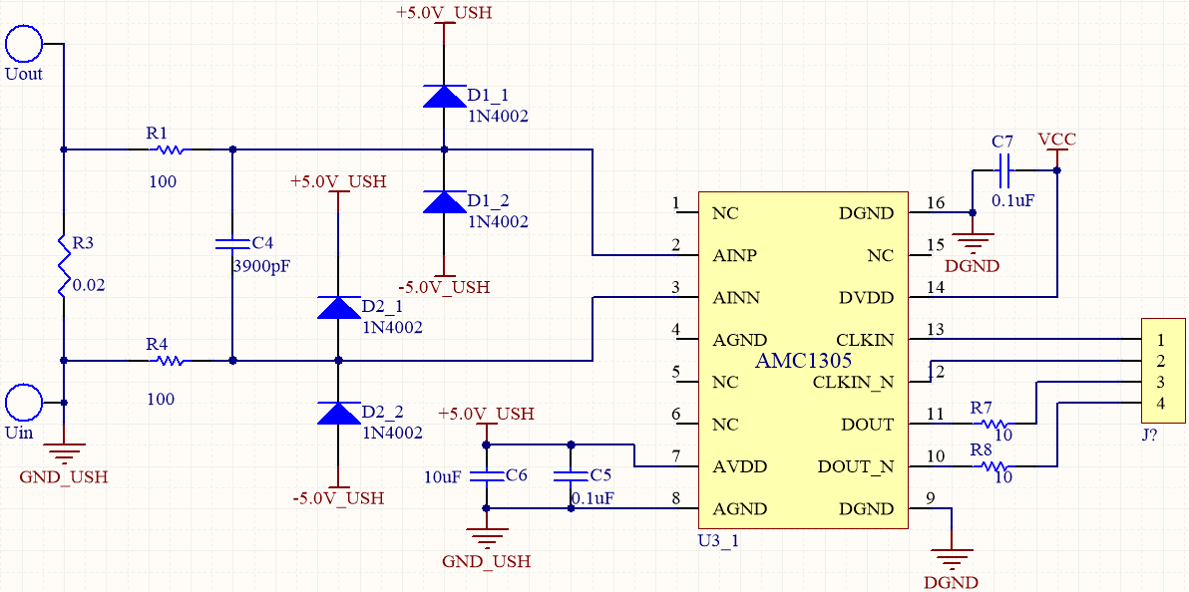
Here is our implement circuit:
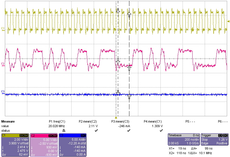
The DOUT of the AMC1305 before connect to FPGA Development Kit (CH1:CLKIN=20MHz, CH2:DOUT of the AMC1305)
The DOUT of the AMC1305 after connect to FPGA Development Kit (CH1:CLKIN=20MHz, CH2:DOUT of the AMC1305)
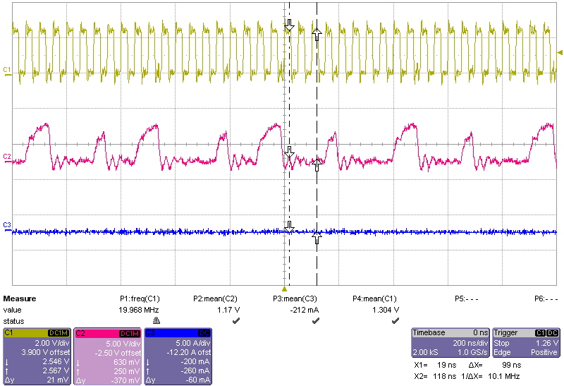
Why the data output changed?
Will this influence the data read by FPGA?
In addition, I want to check the wave of AMC1305 DOUT correct or not
Would you please provide some experiment results? Ex: Full-scale at 50mV (Max) and -50mV (Min)
Thanks!
I have another question about the decimation filter:
Verilog codes follow the pages 16 and 17 in AD7401A datasheet(www.analog.com/.../AD7401A.pdf)
But the output value is wrong...
Have any suggestion about this?
Thanks!
