This thread has been locked.

If you have a related question, please click the "Ask a related question" button in the top right corner. The newly created question will be automatically linked to this question.

ADS1298 - Test Signals and Noise

Other Parts Discussed in Thread: ADS1298

Hello,

I'am working with ADS1298 and XMC4500, trying to capture data from multiple sensors.

So far I am able to start the ADS, write and read registers and change the data rate.

DRDY toggles as intended and I am reading data out in RDATAC mode and send them via ethernet to the PC.

Further processing is done in Matlab. 

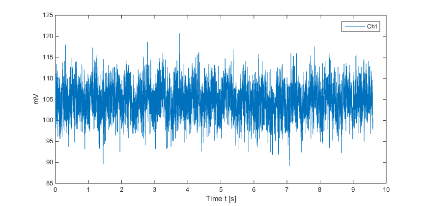
My Problem is, I am noticing a lot of noise on the input channels, way more than the datasheet specifies.

Channel 1, input shorted:

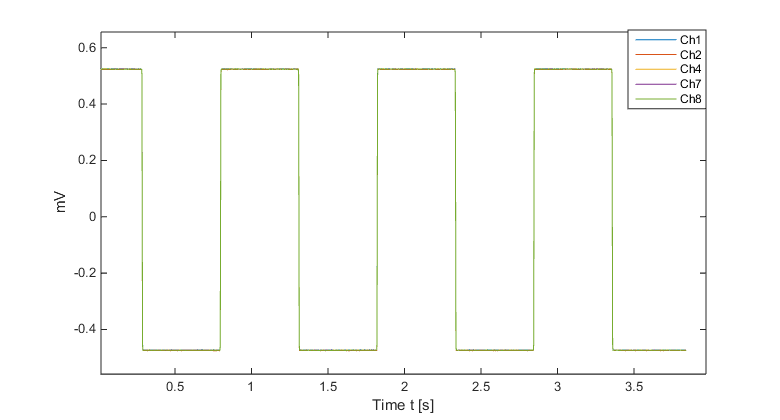
Also the internal test signal seems to be really noisy.

Channel 1, gain 12, source internal test signal:

Another thing I noticed is the test signal is only noticable if I configure the channel with gain 12 (0x65) instead of 6.

My startup process is as follows:

START low

PWDN high

RESET high

wait for power up

send RESET pulse

wait 18 tclk

SPI_send(0x11); // stop RDATAC

//write config registers

reg_write(0x01, 0x86); // high-res , 500 SPS

reg_write(0x02, 0x15); // gen test signals intern

reg_write(0x15, 0x00); // pace disabled

//channel 1-8
reg_write(0x05, 0x65); //test signal

reg_write(0x06, 0x81);
reg_write(0x07, 0x81); 
reg_write(0x08, 0x81); 
reg_write(0x09, 0x81); 
reg_write(0x0A, 0x81); 
reg_write(0x0B, 0x81);
reg_write(0x0C, 0x81);

//gpio ports
reg_write(0x14, 0x00); //output, low

Also my schematic is attached below:

Thanks 

Jonas

  • Hello Jonas,

    Thank you for the time and detail you put into your question. This is good information to work from! When I saw noise coming from the test signal, my gut reaction was that there might be noise on the reference. From your schematic, it looks like you intend to use the internal reference. In the pseudo code you posted, I do not see a write to the CONFIG3 register to turn on internal reference buffer. Perhaps you forgot to include that in your post. If not, you'll need to set bit 7 of the CONFIG3 register. If you intend to use the 4 V reference voltage rather than the 2.4 V reference, you'll also need to set bit 5 of the CONFIG3 register. However, only use the 4 V reference if you are using a 5 V analog supply.

    If the reference is configured correctly and the noise still looks the way it does in your pictures, then I have a couple of questions. Have you manipulated the data in some way to obtain the offset you have in your voltages? The picture of the output is shorted is centered at 105 mV and the test signal is centered at about 160 mV. In both cases I would expect both signals to be centered around 0 V. When you say that the channel 1 input is shorted, do you mean you literally connected the wires? Did you instead configure the CH1SET register to short the inputs internally? If you have not done the latter, I would recommend trying it and seeing what you get.

    Regards,
    Brian Pisani
  • Hello Brian,

    thank your for your quick response. You were right, I forgot to include the line about CONFIG3 register. I am using 4V internal reference, so I set bit 5 in CONFIG3 register, apparently I forgot to enable the reference buffer. So you were correct again, guessing that.

    Now my internal test signals should be fine:

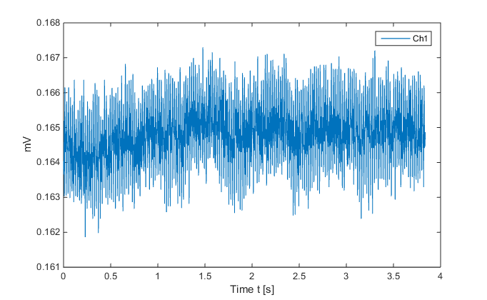
    Also I have shorted inputs of channel 1 externally and measured noise again:

    The 3-4µVPP are inside the datasheets specifications. I am still getting an offset of about 160µV but that should not affect my application.

    Thanks so much again for your help!

    Regards,

    Jonas

  • Jonas,

    No problem. I'm glad you've got it working. Let us know if we can help you with anything else.

    Brian Pisani