This thread has been locked.

If you have a related question, please click the "Ask a related question" button in the top right corner. The newly created question will be automatically linked to this question.

ADS7953 SPI timing/output


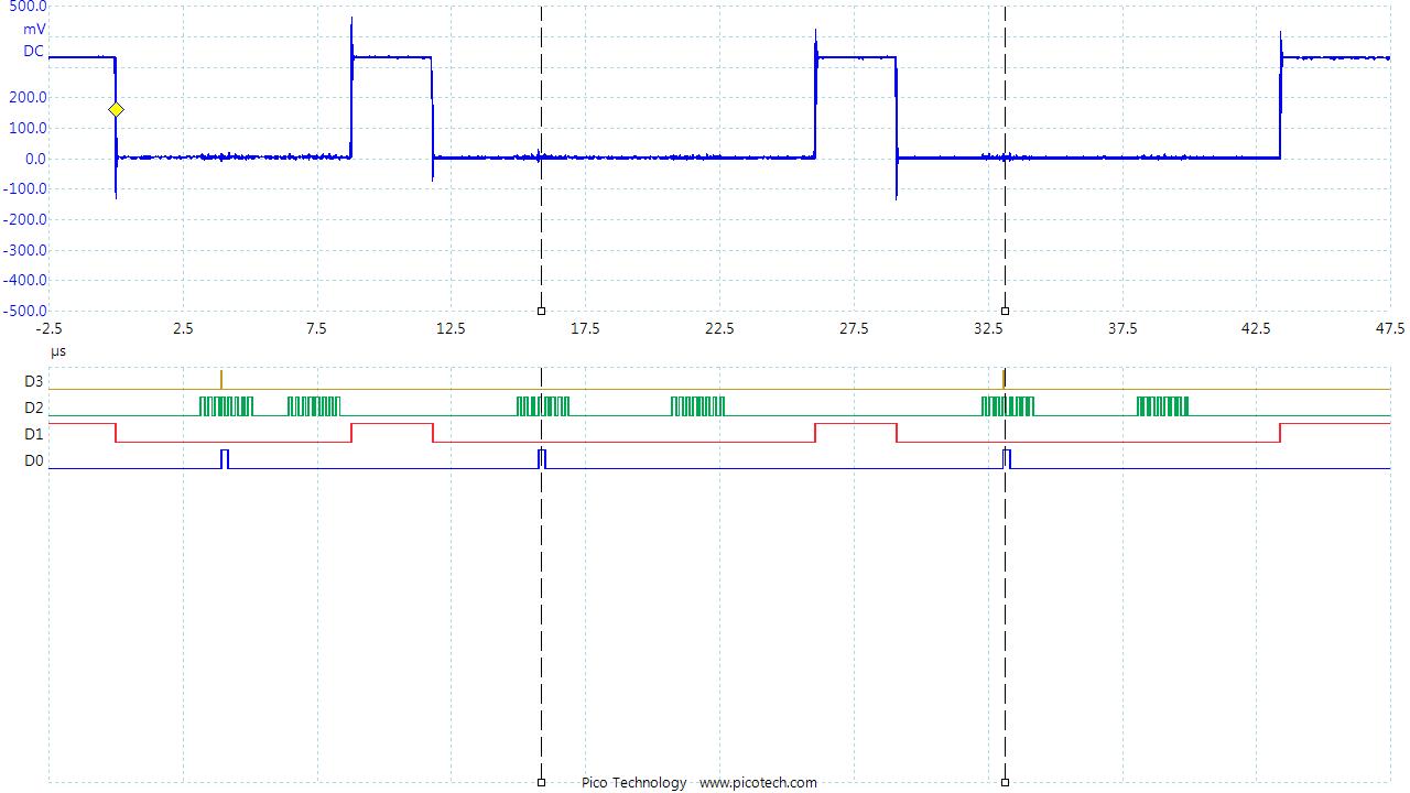
I am struggling with the SPI timing with this device and an MPS430 as the master. The scope shot shows the clock (D2), MOSI (D0), chip select (D1)and output (D3). No output with this arrangement. When I change the clock phase to where the negative clock edges are near the data edges I can get data but scope probe capacitance can affect this. I am clocking out 0x1000 to select manual mode channel 0. 

I am using the extended SPI method as outlined in TI's 4Q 2011 application "Extending the SPI bus for long-distance communication". UCA1 is the sender and UCB1 is the receiver. Clock is 4 Mhz.

What could be my issue?

Thanks.

Edd

  • Edd,

    It does look like your design is marginally with respect to timings.

    Do you have an estimate of the capacitive loads being driven? Are you driving very long traces - you mentioned the TI Whitepaper.

    Please ensure that your SPI controllers configured for CPOL=0, CPHA=1. With this configuration, could you capture zoomed in waveform for the following on the scope:

    - SCLK and SDI at the ADC pins
    - SCLK and SDO at the MSP430 pins

    Regards,
    Sandeep