This thread has been locked.

If you have a related question, please click the "Ask a related question" button in the top right corner. The newly created question will be automatically linked to this question.

ADS1298ECG-FE Body Testing

Other Parts Discussed in Thread: ADS1298
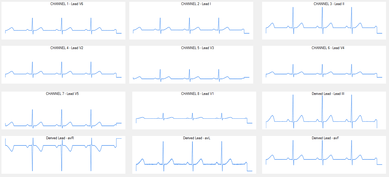
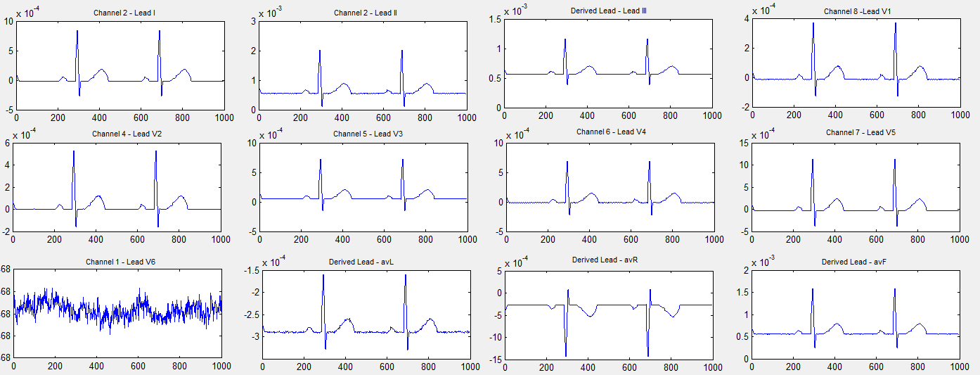
I’ve been working on an ADS1298ECG-FE development for the past few months. I’ve gotten it working with my Teensy 3.1 microcontroller. I attached a plot (first image) of my results that were computed and plotted using Visual Basic. 
I have some questions that I hope someone from TI can help me out with. 
Body Testing
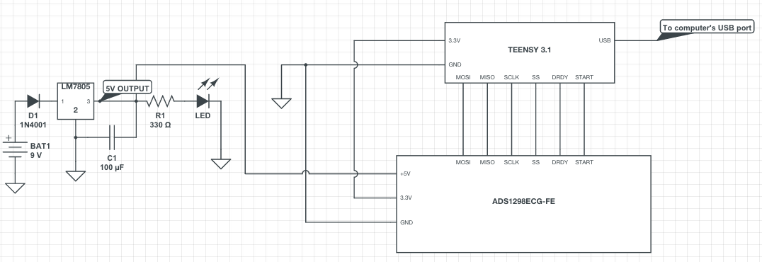
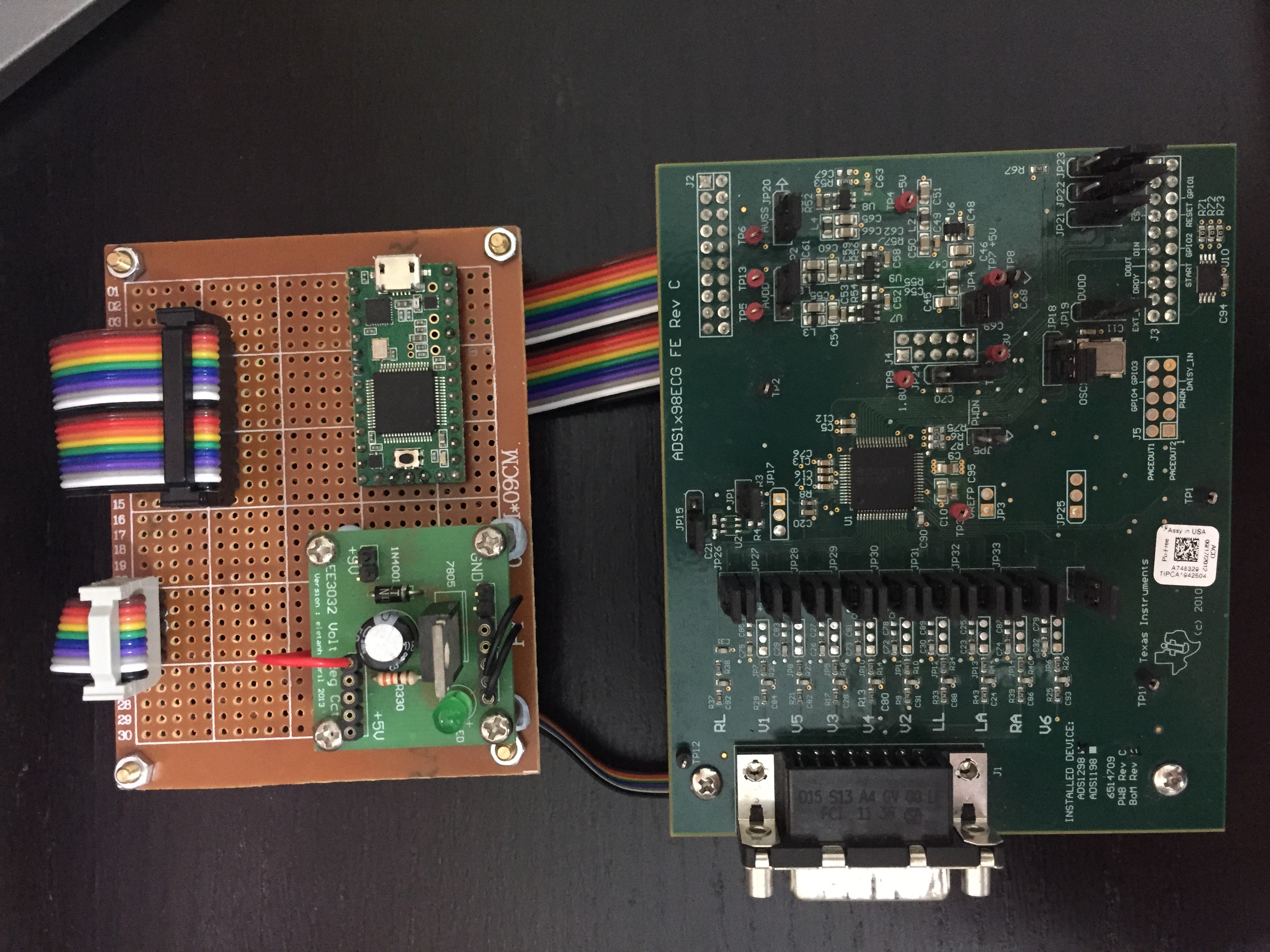
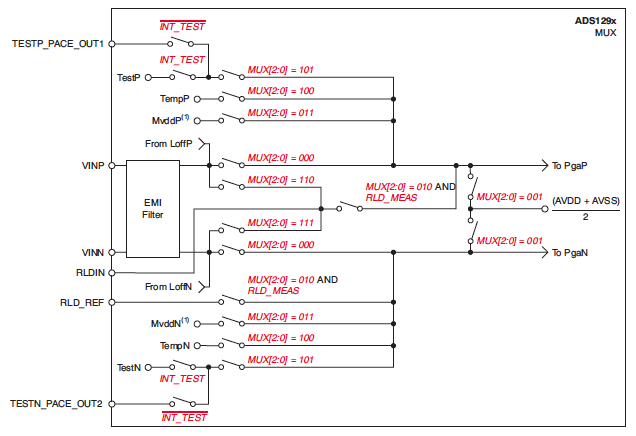
All these while, I’ve been using an ECG simulator (ST-16) to generate the ECG signals. My next task is to carry out body-testing. I have attached the schematic and of the hardware design (second and third image). 
a) Is it safe to carry out testing on my own body with the ADS1298ECG-FE, specifically with my design as shown? 
b) Are there any precautions or things i should take note off? Basically, I’m just seeking clarification and advise if body testing of the ADS1298ECG-FE is safe to be carried out and perhaps some suggestions on how to carry them out safely. 
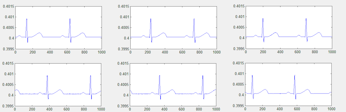
ECG Waveform DC Offset
2) I notice that my ECG waveforms are centered around a DC offset of 0.4. Is this caused by my ECG simulator? (fourth image). 
  • Hello Mohd,

    Unfortunately I'm required to tell you that the ADS1298ECG-FE is intended for electrical evaluation of the features of the ADS1298 in a laboratory, simulation, or development environment, that the ADS1289ECG-FE is not intended for direct interface with a patient, patient diagnostics, or with a defibrillator, and that the ADS1298ECG-FE is intended for development purposes only and is not intended to be used as all or part of an end equipment application. I am not able to give you any advice about body testing.

    I can, however, talk to you about your signal offset. I'd have to imagine that, yes, the offset is produced by the simulator. To make sure, you could always connect the simulator outputs to an oscilloscope and see if you observe the same offset.

    Regards,
    Brian Pisani
  • Hi Brian, 

    Thanks for your quick response. I understand that you're unable to provide advice on body testing so I'll not bother you with that. 

    I'm facing a rather strange problem at the moment that might be linked to the offset produced by the simulator. In the image below, Channel 1 (V6) is suddenly producing a strange waveform that is unusual. This has only started happening today. No changes were made to the code, nor hardware. Could there be any particular why one channel would behave very differently from all other channels (up till 12-lead application) are working just fine. 

    Again, thank you for your help.

    Regards,

    Mohd Aslam

    EDIT: I checked the STATUS word and can confirm that it is not detecting any Lead-Off for V6 lead nor any of the other 9 electrodes. 

  • Hello Mohd,

    From that image, it looks like the lead is not being actively driven. Is the y-axis measured in millivolts? For a proper Lead-Off detection, you'll need to ensure that the control registers contain the right settings. What have you programmed in the following registers: LOFF, LOFF_SENSP, LOFF_SENSN, LOFF_FLIP, CONFIG4?

    Regards,

    Brian

  • Hi Brian, 

    Thanks for your help. I've managed to figure out the problem. It was a trivial issue whereby the CH1SET register was in temperature sensing mode. 

    I have a question regarding temperature sensing of the ADS1298. Hope it's ok to continue adding questions to this thread without starting a new one. Based on pg. 54 of the ADS1298 datasheet, it says that there is an on-chip temperature sensor. I'm not sure if I'm interpreting it correctly 'cos I'm a little confused.

    Is the internal temperature sensor intended measure the temperature of the chip or the patient's body (i.e. electrode) ? Because based on the picture of the Input Multiplexer block, it looks like multiplexing to [2:0] = 100 does not connect the ADS1298 to the VINP and VINN of the electrodes. It selects TEMP and TEMN but i don't see where this goes. With the electrodes connected to the ST-16 ECG simulator, I've tried getting temperature readings and obtained approx. 29 degrees celsius. Putting the electrodes on my hands doesn't change the temperature much. 

    The ultimate question is, what is the temperature sensor measuring. 

    Again, thank you for your help.

    Best regards,

    Aslam

  • Hi Mohd,

    I think in the future it benefits the e2e Community more if you were to post questions about separate topics in separate forums since a member who ran a search for that topic would be able to find a thread that matched his or her search criteria. Thank you for being aware of this!

    The temperature sensor measures the temperature of the chip. This is helpful in case you wished calibrate your conversion data for temperature drift using software that you develop. Let us know if we can help with anything else!

    Regards,
    Brian Pisani