This thread has been locked.

If you have a related question, please click the "Ask a related question" button in the top right corner. The newly created question will be automatically linked to this question.

DAC161S997 self powered design

Other Parts Discussed in Thread: DAC161S997

Hi

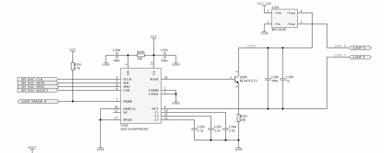
We are using DAC161S997 to create a 4..20 mA current loop. Our system has an MSP430 as controller for the DAC and an additional PWM channel to drive a heater. As the heater current is to high, we cannot go for a loop powered design.

Our design runs of 24V DC. We generate a 3.3V supply (VCC) using an LDO. 3.3V is used to power the DAC, MSP430 and some OpAmps. We have an isolating DC/DC converter to generate our loop voltage, which is isolated from the rest of the system.

Our devices constantly die out in the field. We don't know the reason. One thing is, if the customer connects one of the LOOP_x to GND, it will not work (as expected). 

If the DAC is dead it will generate loop errors.

Any ideas what could be wrong with the DAC or the configuration? Do we need any protection? Is the DAC interface sensitive to EMV / ESD?

Thank you

Alex

  • Hi Alex,

    In this circuit, connecting LOOP N (or LOOP P) to ground shorts out the 40R resistor inside the DAC161S997 device, so the device will not work.

    If you look at Figure 16 on page 18 of the datasheet (SNAS621A), it shows R1 (80k) and R2 (40R). Equation 1 (on the previous page) gives the equation for the loop current as:

    I_LOOP = (1 + R1/R2) I_DAC

    What are you connecting between LOOP P and LOOP N? It should be an ammeter or a resistor. The voltage across the resistor would be between 1 and 5V, if the resistor was 250R and the current was between 4 and 20mA.

    EDIT: There is a limit on the maximum resistance between LOOP P and LOOP N.  If you go above it, too much of the 24V will be dropped across the resistor and you will get loop errors, since the required output current can't be sustained. 

    EDIT: Connecting LOOP P to ground shorts the 40R resistor and connecting LOOP N to ground bypasses it.  Either way there will be no voltage across the resistor. 

    EDIT: I think I may have misunderstood you; I thought you were saying that you expected it to work when you grounded a loop terminal, instead of not expecting it to work.  Your loop voltage is not isolated from the rest of the system, as there will be a resistance between -Vin and -Vout (of U201) of 40R plus the resistance between the loop terminals.  The lack of isolation could be the reason for the chip deaths.  You can't isolate the DAC161S997 from the current loop.  You can isolate the loop and DAC from the rest of the system though, by moving the DAC's 3.3V LDO to the isolated 24V supply, having a separate 3.3V LDO for the rest of the circuitry and having optocouplers on the SPI lines.  Is there any kind of reverse polarity protection?

    The breakdown voltages of the transistor will dictate the maximum voltage, rather than the DAC itself.  If you get a spike over 45V (the value of Vceo for Q200), the DAC will die.