This thread has been locked.

If you have a related question, please click the "Ask a related question" button in the top right corner. The newly created question will be automatically linked to this question.

ADS7844 sensitivity

Other Parts Discussed in Thread: ADS7844

I am using the ADS7844 in a DCDC converter. It is used for multiple measurement, bu also the output voltage of the DCDC converter.

I measure ~500ns jitter on the PWM signals of the DCDC converter. I located the routcause of the jitter at the input of the ADS7844. I have placed a R-C filter (330 [Ohm], 560 [pF]) at each ADC input. The signals measures very steady when I measure before the RC filter. As soon as I connect the voltage probe across the 560pF capacitor (thus direct on the ADC input pin), the jitter becomes a lot worse: >2us.

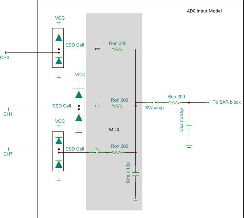
So I am focussing on the input configuration of the ADC. It is extremely sensitive. Can somebody help me with possible rootcauses / solutions? If I know the ADC input configuration I can do a simulation.

Thanks

  • Hello Johan,

    It would be helpful if you could provide more detailed information about the problem you are observing.

    Could you please post oscilloscope plots of the following signals?
    1) the switching regulator output waveform
    2) the ADC input waveform along with a description of how you're measuring its jitter

    A schematic of your ADC block would also be very helpful.

    A few additional questions:

    - What is the state of the ADC when you take your jitter measurements? Is it actively converting or simply powered on and left in a quiescent state?

    - What kind of switching regulator is this? Please note that the ADC input is not a high impedance port. It consumes load current during acquisition and perhaps what you're observing is an effect of the dynamic interaction between the power converter output impedance and the ADC input load

    - Have you tried inserting an op amp buffer between the regulator output and the SAR ADC input for isolating the ADC load?

    Below is an approximate representation of the ADC input:

    Regards,
    Harsha Munikoti

  • Hello,

    Hereby the scope plot of the requested signals. It can be observed that the ADC input voltage is clean, while the output jitters. I also noticed that the jitter is very large (~2usec) when I connect a probe at the ADC input. Without a probe the jitter is ~0.5usec.

    Hereby the schematic:

    Sch_PB_R06.pdf.pdf

    - What is the state of the ADC when you take your jitter measurements? Is it actively converting or simply powered on and left in a quiescent state?

    actively converting

    - What kind of switching regulator is this? Please note that the ADC input is not a high impedance port. It consumes load current during acquisition and perhaps what you're observing is an effect of the dynamic interaction between the power converter output impedance and the ADC input load

    please explain your question. I do not understaand what you are questioning.

    - Have you tried inserting an op amp buffer between the regulator output and the SAR ADC input for isolating the ADC load?

    Yes, this is in place.


    please email me directly if attachements are not good to read: johan.vissers@prodrive-technologies.com 

    regards

    Johan

  • Hi Johan,

    First of all, could you please clarify the following?

    - With reference to the schematic, at which points exactly are you monitoring the "switching regulator output" and the "ADC input"?

    - How do you know that the jitter is 500ns when the scope probe is not connected?

    From an initial analysis, it looks like your regulator may be very sensitive to load current changes at its output. Not only is the regulator driving a switching voltage signal across the load, but there is also loading due to switching activity at the ADC input. Evidently, this is modulating the pulse width of the PWM signal which is producing excessive noise at the ADC input (~2us of peak-to-peak jitter producing 500mVp-p of noise at the ADC input). Besides, you mention that the jitter is sensitive to something as small as scope probe capacitance. 

    Have you tried monitoring the output of the regulator under the following conditions:
    - with no ADC activity?
    - entirely disconnecting the filter and ADC from the PWM source?

    It will be interesting to see how the PWM signal changes under these conditions.

    Also, what is the source of the PWM signal? Are you using an off-the-shelf IC or do you have a discrete circuit for generating it? Any details you could share would be useful.

    I also noticed that you have multiple voltage inputs and two variants of the signal path (2 different filter cutoffs) to process them. Again, it would be helpful if you could describe your application in more detail. 

    Thanks,
    Harsha