This thread has been locked.

If you have a related question, please click the "Ask a related question" button in the top right corner. The newly created question will be automatically linked to this question.

ADS1248, AIN0-7 dependability, and filter settling

Other Parts Discussed in Thread: ADS1248

Hello,

I have two question:

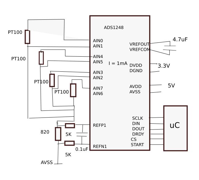
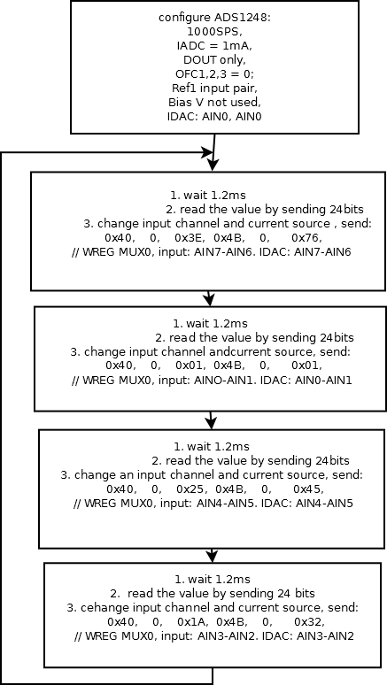
1. I'm reading a room temperature value using one ADS1248 and uC with four  three wire PT100.The software multiplex the AINs tofor each PT100 and all PT100 use the same Rref.

 The reading seems to be fine until I test puling out a cable of one of PT100 to simulate sensor failure.

Then the  values from other, connected, three sensors are all false! After connecting the sensor back the all values are again fine.

Can somebody please explain why is this happening? Are the channels dependant of each other? What is happening to other channels when ADS once read  the false value, i.e the value without a sensor input?

2.  Can somebody please explain the connection between digital filter reset and conversion time. In particular connection between tables 16 and 15 from the ads1248 documentation, since in my application I'm using multiplexing on 4 channels and therfore changing the MUX0 value, thereby every time reseting the filter according to documentation.

Thank you in advance.

  • Igor,


    If you have a schematic that you are able to post, that might be helpful to debug your problem.

    There shouldn't be any channel dependence when cycling from channel to channel, but you may need to worry about the voltages settling when you are cycling in such a way.

    Without seeing the schematic, I might guess that you are seeing some delay in settling in the measurement as you move the excitation current from channel to channel. As an example, you may have extra capacitance across the RTD or the reference resistor that requires more settling time as the current is lost for one of the channels. You might be able to confirm that with an oscilloscope measurement of the reference input.

    If that isn't the problem, post the data that you are getting. This would include the raw digital data for the input when the readings are good and when the readings are bad. I'd also want to know the input and reference voltages and the excitation current with the resistor and RTD values. I also would like to know about how you have the device set up and how you cycle through channels.

    As for the digital filter reset and conversion time, the tables just describe how long it takes for a conversion to be completed. The digital filter takes the input and filters it for the entire length of the conversion time. When the data finally comes out, the output data should be settled, presuming that the input voltage is settled as well.


    Joseph Wu
  • Hello Josep,

    Thank you.

    the set - up is here:

    The whole set-up is done on a PCB, with general EMC requirements followed. The filter on the REF input is the only pleasible solution so far found  for unstability of data reading. which is now ~ 0.005 °C, please see the link bellow in which I discussed the problem and you suggested solution:

    e2e.ti.com/.../402204

    The software miltiplexes as following:

    Thank you for your time,

    Kind regards,

    Igor J.

  • Hello Joseph,

    I've just noticed a mistake on the schematic above the AIN6 is also connected

    Thank you
  • Igor,

    Thanks for the schematic and the flow diagram, it helps. What IDAC currents are you using and what is the data rate? I would also like to see some of the resulting data though with the expected voltage and the raw data from the ADC. It might also help with debugging if you slow it down and make a few readings per channel to see if it settles over time. Or you could increase the time between each reading to see if it settles.

    Right now I think that the problem is the settling of the reference. If you remove the AIN7-AIN6 PT100 (which is the first channel in the flow diagram), then the IDAC current going to the reference resistor drops because none of the positive side current. This is fine for the AIN7-AIN6 PT100 device that is now gone, because this will read a full scale measurement.

    However, as the IDACs move to the next channel for the AIN0-AIN1 PT100 reading, you still start off with a low voltage across the reference resistor since the last measurement had an IDAC current was could not be sourced because of the missing AIN7-AIN6 PT100. With the reference, you have a 0.1uF with almost 11k of resistance. This gives an RC time constant of over 1ms, which is the same order of measurement.

    One thing you could try would be to remove the 5k resistors in series with the reference and the 0.1uF and try making the measurements again. This would reduce the setting time with any capacitance being the parasitic capacitance of the board and reference inputs.

    Joseph Wu

  • Just to close out this post, Igor mentioned in a different post:

    "By the way, if you want to know the solution for a problem I posted a couple weeks ago, (see link bellow), as you suggested, after multiplexing additional waiting time of about 2ms help channels to settle and solved the problem. Therefore the channels are now independed and failure of one sensor won't influence other values."

    With the IDAC being routed to an open position, it required extra time for the ADC to recharge the VREF capacitance and get correct readings again.


    Joseph Wu