This thread has been locked.

If you have a related question, please click the "Ask a related question" button in the top right corner. The newly created question will be automatically linked to this question.

ADS1299 Power Supply

Other Parts Discussed in Thread: ADS1299

Hi Team,

Our customer is using the ADS1299IPAGR (24-bit, EEG DAC), along with TPS73225/72325s wondering if:

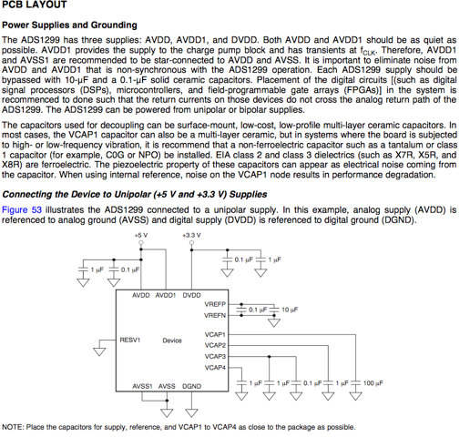
1) +2.5V/-2.5V supply filtering is necessary for each individual implementation of one of these ADCs? Or could a pair of them share a supply filter? They plan on configuring the ADCs in a Daisy-Chain config. It stands to reason that each ADC might need its own isolated supply, but I don’t see it explicitly stated in the datasheet as shown below.

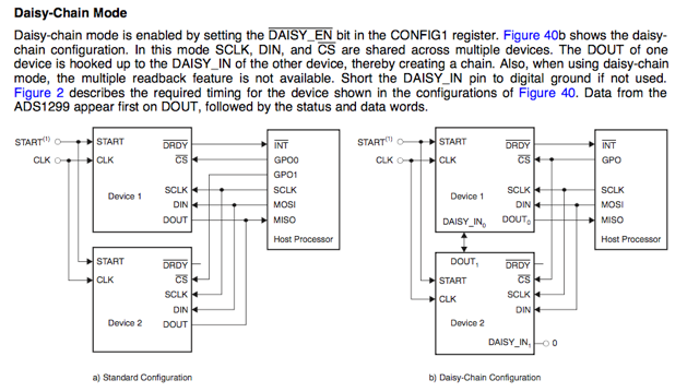
2) Is there a mode where we would be able to route two specific channels in a
differential pair to one-another? That is, instead of a each channel pair (in bipolar mode) being connected to an amp, we would instead route the positive
side of one channel, to the negative side of another? I can see where there is some description involving input multiplexing for EEG specific functions, but
it seems to pertain to the BIAS drive signal only.


Thanks for your help!

,Nabeel

  • Hey Nabeel,

    When you say filtering, I’m assuming you’re referring to the bypass capacitors used to decouple the supply from unwanted noise. If that is the case, then yes, every ADC should have its own dedicated supply decoupling capacitors. If you’re looking to reconcile Figures 40 and 53, then imagine that every individual ADS1299 in Figure 40 has its power supplies configured like that in Figure 53.

    Unfortunately for this device it is not possible to route individual channel inputs to other channels, but I would look into using the SRB pins. You can find a helpful functional diagram of the input MUX in Figure 19 on page 16 of the datasheet. You’ll see that the SRB2 pin can serve as the positive input to any channel if the correct bit is set in the CHnSET register for that channel and the SRB1 pin can serve as the negative input to all the channels if its corresponding bit is set in the MISC1 register. I’m not sure if this provides you with the desired flexibility, but it’s worth looking into.

    Regards,

    Brian Pisani

  • Thanks for your help Brian!