This thread has been locked.

If you have a related question, please click the "Ask a related question" button in the top right corner. The newly created question will be automatically linked to this question.

ADS1298FE WCT and Lead-off problem

Other Parts Discussed in Thread: ADS1298

Hi everyone!

My ADS1298FE performs strange for ECG usage.

The lead off warning always turn red for the negative input that connect to V1 - V6. For the inputs that connect to the legs and arms, they looks great.

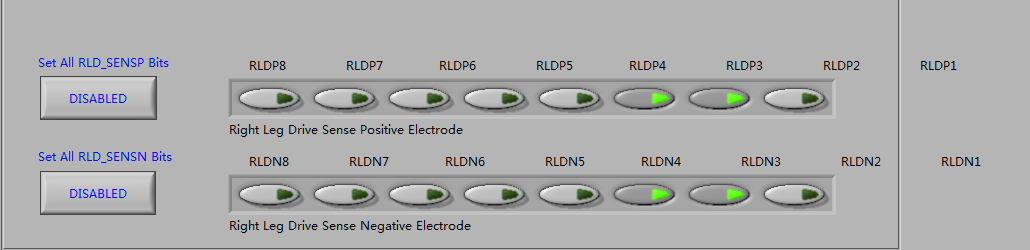
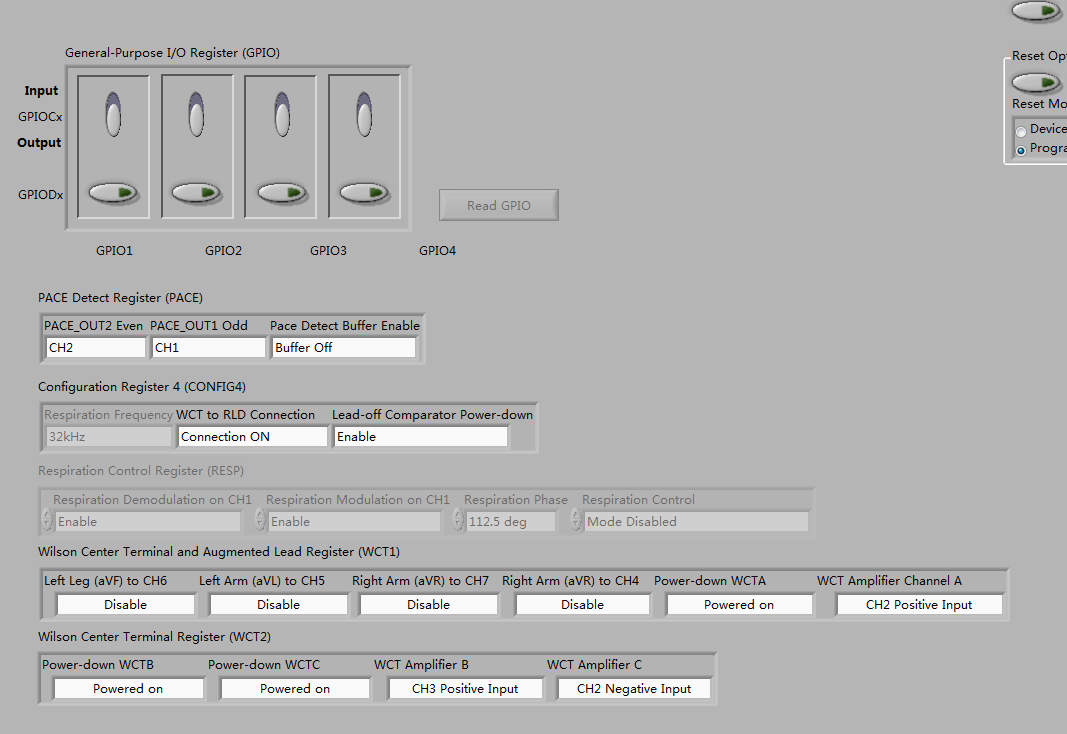
So I guess my WCT output on ADS1298 has something wrong.

Since the lead-off detection applied a load detection way, I thought that the WCT output can be a load both for positive and negative input. So the WCT is connect to the positive input, to check if the WCT is in trouble. However, when the WCT connect to the positive input, the lead-off warning turns green for the positive one! 

I don't know why the WCT fail for the negative inputs while they success for the positive inputs.

And since the V1-V6 is lead-off, the board could not use for ECG measure. No signal is detect for the V1-V6. Although signals for Leads looks well.

I tried to measure the output voltage of the WCT output, it is 0.7V in average. Is it all right?

Please tell me how to fix that.

Thanks for your kind help!

Wendi

  • Hello,
    I am facing a similar problem.
    I get leads-off detection status for all leads except RA lead.

    Can someone suggest why this happens ??

    Warm regards,
    Abhishek.
  • Hello Wendi,

    You say that you are getting leads-off for RA,LA and LL.

    Can you please share the values that you have put in all the config registers and the ADS1298 connections??

    Thank you in advance.

    Warm regards,

    Abhishek.

  • Hey Wendi,

    Which signals are you using as your inputs to the WCT amps? The output of the WCT pin will be the average of the inputs that are specified in the WCT1 and WCT2 registers. Knowing those settings as well as your settings for the lead-off detection will help me determine what might be causing the issue.

    Regards,
    Brian Pisani
  • Hi, Abhishek!

    My setting are like following pictures

    For channels:

    For right leg drive

    For WCT

    I think that's all the settings. And I'm sure that they worked.

    Hope these settings can help you fix the problem.

    Regards,

    Wendi

  • Hi Brian,

    Thanks for your reply.

    I've trun on the power for  WCTA, WCTB and WCTC. They are LL, LA, RA.

    The WCT1 and WCT2 registers are setting as follows,

    And for lead off setting,I use that shown in PDK. That is to enable all LOFFP bits and the LOFFN2 bit, while others are not enabled. These setting used to work out well. There were ECG waves on the scope.

    However, I tried the same setting, and the lead off problem came out. I tried to change the lead-off setting, but they donot work any more. Turned on all the LOFFN bits resulted in the same lead-off warning.

    Thanks for your kind help.

  • Hello Wendi,
    Thank you very much for replying.
    I got all the settings, but can you please tell me what value have you put in LOFF_FLIP register ??

    Warm regards,
    Abhishek.
  • Hello Wendi,
    I implemented your settings, but i didn't get leads-off.
    Can you share your Device Registers from "Register Map" tab from the Evaluation software??

    Regards,
    Abhishek.
  • Hi Abhishek,
    The LOFF FLIP were turned off.
    Sorry I didn't save the Register Map when my board worked well. They worked when it set as the picture shows.
    My board has something wrong, the register map may also got some wrong now.
    Hope we can find out the problem soon.
  • Hello Wendi,

    When i Device Defaults, i get leads-off for Right Arm lead but not for Left Leg(LL lead) and V5(Chest Lead).

    Can you please check you device leads-off status in Device Defaults condition and reply??

    That would be very helpful.

    Regards,

    Abhishek.

  • Hi Wendi,

    Thanks for your detailed response. When you said the voltage at your WCT pin was 0.7 V, is that with respect to AVSS? If that is the case, it may be low enough to trigger the lead-off comparators. You were partially right about how the lead-off detection works. It's not as much load measurement as it is voltage measurement. The lead-off comparators on the negative side will rail if the voltage at the input gets too low which, when the load is high, tends to happen. However, the load does not need to be high for the negative input voltage to be close to AVSS. Since the WCT output, which you are feeding to the negative inputs, should be the average of the LL, LA, and RA voltages since you said those were the leads that you were using as your input to the WCT amps, is that the voltage you expect? Probe the LL, LA, and RA leads yourself and calculate the average. If the average should in fact be 0.7 V, then the lead-off comparator is triggering simply because the input to the negative leads is too low. You could fix that by increasing the common mode input voltage on the positive leads to something that won't trigger the negative lead-off comparators.

    Regards,
    Brian Pisani
  • Hi Brian,
    Thanks for you reply.
    I have another problem to probe the LL,LA and RA. I guess there should be a "ground" or reference voltage while the positive probe click on LL, LA or RA. Is it okay to click the GND on the board as negative probe?
    I could not figure out the reference ground for the inputs, because I thought that the LL, LA and RA generated WCT which worked as a ground or reference voltage for the V1-V6.
    Many thanks!
  • Hi Abhishek!
    My board worked well when it was applied default setting.
    BTW, if you got problem only for LL and V5, you may try to turn off the WCT amplifier for LL. I'm not sure but maybe that will ignore the LL and give right WCT for the V1-V6.
    Hope that could help you.
  • Hi Wendi,
    That seems strange because when i apply default settings to my board, i don't get leads off as desired.
    Maybe, i'll just check with the connections on the board and lead voltages when leads are off.

    Thanks and regards,
    Abhishek.
  • Hey Wendi,

    All of the inputs will be measured differentially. The output you receive will be [(INxP - INxN)*PGA gain] no matter what those inputs are tied to (as long as they do not rail the PGA or clip the reference). The WCT output is sometimes applied to the negative inputs of the channels as a reference since is is typically configured as the average of some of the input voltages. Hopefully this answers your question.

    Regards,
    Brian Pisani