This thread has been locked.

If you have a related question, please click the "Ask a related question" button in the top right corner. The newly created question will be automatically linked to this question.

acquiring respiration waveform from ads1292r

Other Parts Discussed in Thread: ADS1294, ADS1296, ADS1298, ADS1294R, ADS1296R, ADS1298R, ADS1292R

Hi,

This is my program done using Chipkit uno32

#include <SPI.h>


//---------------------------------------------------------------------------------

// vars


String sep = "---------------------------------------------------------";

boolean debug_msg                      = true;

int n_channels                                  = 0;

int blank                                               = 0;


// SPI

//#define DOUT 7 //MOSI

//#define DIN 8 //MISO

//#define SPICK 14 //SCK


// pins

#define PIN_CS  8

#define PIN_RESET  7

#define PIN_START  11

#define PIN_DRDY  4

#define PIN_LED  13


// register commands

#define READ  0x20

#define WRITE  0x40


// other

int gMaxChan = 2;

int gNumActiveChan = 2;

int activeSerialPort = 0; //data will be sent to serial port that last sent commands. E.G. bluetooth or USB port

boolean gActiveChan [2]; // reports whether channels 1..2 are active

boolean isRDATAC = true;


enum spi_command {

                // system commands

                WAKEUP = 0x02,

                STANDBY = 0x04,

                RESET = 0x06,

                START = 0x08,

                STOP = 0x0a,


                // read commands

                RDATAC = 0x10,

                SDATAC = 0x11,

                RDATA = 0x12,


                // register commands

                RREG = 0x20,

                WREG = 0x40,

};


enum reg {

                // device settings

                ID = 0x00,


                // global settings

                CONFIG1 = 0x01,

                CONFIG2 = 0x02,

                LOFF = 0x03,


                // channel specific settings

        CHnSET = 0X03,

                CH1SET = CHnSET + 1,

                CH2SET = CHnSET + 2,


                // lead off status

                RLD_SENS = 0x06,

                LOFF_SENS = 0x07,

                LOFF_STAT = 0x08,


                // other

                GPIO = 0x0B,

                RESP1 = 0x09,

                RESP2 = 0x0A,


};


enum ID_bits {

                DEV_ID7 = 0x00,

                DEV_ID6 = 0x40,

                DEV_ID5 = 0x20,

        DEV_ID4 = 0x10,

                DEV_ID2 = 0x04,

                DEV_ID1 = 0x02,

                DEV_ID0 = 0x01,


                ID_const = 0x10,

                ID_ADS129x = DEV_ID7,

                ID_ADS129xR = (DEV_ID7 | DEV_ID6),


                ID_4CHAN = 0,

                ID_6CHAN = DEV_ID0,

                ID_8CHAN = DEV_ID1,


                ID_ADS1294 = (ID_ADS129x | ID_4CHAN),

                ID_ADS1296 = (ID_ADS129x | ID_6CHAN),

                ID_ADS1298 = (ID_ADS129x | ID_8CHAN),

                ID_ADS1294R = (ID_ADS129xR | ID_4CHAN),

                ID_ADS1296R = (ID_ADS129xR | ID_6CHAN),

                ID_ADS1298R = (ID_ADS129xR | ID_8CHAN)

};


enum CONFIG1_bits {

                SINGLE_SHOT = 0x00,

        BIT6 = 0x00,

        BIT5 = 0x00,

        BIT4 = 0x00,

        BIT3 = 0x00,

                DR2 = 0x00,

                DR1 = 0x02,

                DR0 = 0x00,


                CONFIG1_const = 0x02,

        //SAMP_125_SPS = CONFIG1_const,

        //SAMP_250_SPS = (CONFIG1_const | DR0),

        SAMP_500_SPS = (CONFIG1_const | DR1),

        //SAMP_1_KSPS = (CONFIG1_const | DR1 | DR0),

        //SAMP_2_KSPS = (CONFIG1_const | DR2),

        //SAMP_4_KSPS = (CONFIG1_const | DR2 | DR0),

        //SAMP_8_KSPS = (CONFIG1_const | DR2 | DR1)


};


enum CONFIG2_bits {

                PDB_LOFF_COMP = 0x00,

        PDB_REFBUF = 0x20,

        VREF_4V = 0x00,

        CLK_EN = 0x08,

                INT_TEST = 0x00, //amplitude = ±(VREFP – VREFN) / 2400

                TEST_FREQ = 0x00,


                CONFIG2_const = 0x80,

                INT_TEST_1HZ = (CONFIG2_const | INT_TEST | TEST_FREQ),

                INT_TEST_DC = (CONFIG2_const | INT_TEST)

};


enum LOFF_bits {

                COMP_TH2 = 0x00,

                COMP_TH1 = 0x00,

                COMP_TH0 = 0x00,

                VLEAD_OFF_EN = 0x10,

                ILEAD_OFF1 = 0x00,

                ILEAD_OFF0 = 0x00,

                FLEAD_OFF1 = 0x00,

                FLEAD_OFF0 = 0x00,


                LOFF_const = 0x10,


                COMP_TH_95 = 0x00,

                COMP_TH_92_5 = COMP_TH0,

                COMP_TH_90 = COMP_TH1,

                COMP_TH_87_5 = (COMP_TH1 | COMP_TH0),

                COMP_TH_85 = COMP_TH2,

                COMP_TH_80 = (COMP_TH2 | COMP_TH0),

                COMP_TH_75 = (COMP_TH2 | COMP_TH1),

                COMP_TH_70 = (COMP_TH2 | COMP_TH1 | COMP_TH0),


                ILEAD_OFF_6nA = 0x00,

                ILEAD_OFF_12nA = ILEAD_OFF0,

                ILEAD_OFF_18nA = ILEAD_OFF1,

                ILEAD_OFF_24nA = (ILEAD_OFF1 | ILEAD_OFF0),


                FLEAD_OFF_AC = FLEAD_OFF0,

                FLEAD_OFF_DC = (FLEAD_OFF1 | FLEAD_OFF0)

};


enum CHnSET_bits {

                PDn = 0x00,

                PD_n = 0x00,

                GAINn2 = 0x00,

                GAINn1 = 0x00,

                GAINn0 = 0x00,

                MUXn2 = 0x00,

                MUXn1 = 0x00,

                MUXn0 = 0x00,


                CHnSET_const = 0x00,


                GAIN_1X = GAINn0,

                GAIN_2X = GAINn1,

                GAIN_3X = (GAINn1 | GAINn0),

                GAIN_4X = GAINn2,

                GAIN_6X = 0x00,

                GAIN_8X = (GAINn2 | GAINn0),

                GAIN_12X = (GAINn2 | GAINn1),


                ELECTRODE_INPUT = 0x00,

                SHORTED = MUXn0,

                RLD_INPUT = MUXn1,

                MVDD = (MUXn1 | MUXn0),

                TEMP = MUXn2,

                TEST_SIGNAL = (MUXn2 | MUXn0),

                RLD_DRP = (MUXn2 | MUXn1),

                RLD_DRN = (MUXn2 | MUXn1 | MUXn0)

};


enum CH1SET_bits {

                PD_1 = 0x00,

                GAIN12 = 0x00,

                GAIN11 = 0x00,

                GAIN10 = 0x00,

                MUX12 = 0x00,

                MUX11 = 0x00,

                MUX10 = 0x00,


                CH1SET_const = 0x00

};


enum CH2SET_bits {

                PD_2 = 0x00,

                GAIN22 = 0x40,

                GAIN21 = 0x20,

                GAIN20 = 0x00,

                MUX22 = 0x00,

                MUX21 = 0x00,

                MUX20 = 0x00,


                CH2SET_const = 0x00

};


enum RLD_SENSP_bits {

                RLD8P = 0x00,

                RLD7P = 0x00,

                RLD6P = 0x00,

                RLD5P = 0x00,

                RLD4P = 0x00,

                RLD3P = 0x00,

                RLD2P = 0x00,

                RLD1P = 0x00,


                RLD_SENSP_const = 0x00

};


enum RLD_SENSN_bits {

                RLD8N = 0x00,

                RLD7N = 0x00,

                RLD6N = 0x00,

                RLD5N = 0x00,

                RLD4N = 0x00,

                RLD3N = 0x00,

                RLD2N = 0x00,

                RLD1N = 0x00,


                RLD_SENSN_const = 0x00

};


enum LOFF_SENSP_bits {

                LOFF8P = 0x00,

                LOFF7P = 0x00,

                LOFF6P = 0x00,

                LOFF5P = 0x00,

                LOFF4P = 0x00,

                LOFF3P = 0x00,

                LOFF2P = 0x00,

                LOFF1P = 0x00,


                LOFF_SENSP_const = 0x00

};


enum LOFF_SENSN_bits {

                LOFF8N = 0x00,

                LOFF7N = 0x00,

                LOFF6N = 0x00,

                LOFF5N = 0x00,

                LOFF4N = 0x00,

                LOFF3N = 0x00,

                LOFF2N = 0x00,

                LOFF1N = 0x00,


                LOFF_SENSN_const = 0x00

};


enum LOFF_FLIP_bits {

                LOFF_FLIP8 = 0x00,

                LOFF_FLIP7 = 0x00,

                LOFF_FLIP6 = 0x00,

                LOFF_FLIP5 = 0x00,

                LOFF_FLIP4 = 0x00,

                LOFF_FLIP3 = 0x00,

                LOFF_FLIP2 = 0x00,

                LOFF_FLIP1 = 0x00,


                LOFF_FLIP_const = 0x00

};


enum LOFF_STATP_bits {

                IN8P_OFF = 0x00,

                IN7P_OFF = 0x00,

                IN6P_OFF = 0x00,

                IN5P_OFF = 0x00,

                IN4P_OFF = 0x00,

                IN3P_OFF = 0x00,

                IN2P_OFF = 0x00,

                IN1P_OFF = 0x00,


                LOFF_STATP_const = 0x00

};


enum LOFF_STATN_bits {

                IN8N_OFF = 0x00,

                IN7N_OFF = 0x00,

                IN6N_OFF = 0x00,

                IN5N_OFF = 0x00,

                IN4N_OFF = 0x00,

                IN3N_OFF = 0x00,

                IN2N_OFF = 0x00,

                IN1N_OFF = 0x00,


                LOFF_STATN_const = 0x00

};


enum GPIO_bits {

                GPIOC2 = 0x00,

                GPIOC1 = 0x00,


                GPIOD2 = 0x00,

                GPIOD1 = 0x00,


                GPIO_const = 0x0C,

};


enum RESP1_bits {

                RESP_DEMOD_EN1 = 0x80,

                RESP_MOD_EN1 = 0x40,

                RESP_PH2 = 0x00,

                RESP_PH1 = 0x08,

                RESP_PH0 = 0x00,

                RESP_CTRL1 = 0x02,

                RESP_CTRL0 = 0x00,


                RESP1_const = 0x00,


                RESP_PH_22_5 = 0x00,

                RESP_PH_45 = RESP_PH0,

                RESP_PH_67_5 = RESP_PH1,

                RESP_PH_90 = (RESP_PH1 | RESP_PH0),

                RESP_PH_112_5 = RESP_PH2,

                RESP_PH_135 = (RESP_PH2 | RESP_PH0),

                RESP_PH_157_5 = (RESP_PH2 | RESP_PH1),


                RESP_NONE = 0x00,

                RESP_EXT = RESP_CTRL0,

                RESP_INT_SIG_INT = RESP_CTRL1,

                RESP_INT_SIG_EXT = (RESP_CTRL1 | RESP_CTRL0)

};

enum RESP2_bits {

  CALIB_ON = 0x00,

  RESP_FREQ = 0x00,

  RLDREF_INT = 0x02,

  BIT0 = 0x01,

  RESP2_const = 0x02,

};


// serial api

boolean read_ads_data                                = false;

boolean serial_send_data           = false;

boolean valid_cmd               = false;

enum SERIAL_API {

                S_READ_ADS = 0x67,//                                  = 0xBF,                 // read from the ads

                S_STOP_READ_ADS = 0x73, //   = 0xFD,                 // stop reading freom the ads

                S_SEND_SERIAL                                = 0xDF,                 // start sending to the serial interface

                S_STOP_SEND_SERIAL = 0xFB                   // stop streaming to the serial interface

};


//---------------------------------------------------------------------------------

// functions


//utilities

#include <stdarg.h>


String hex_to_char(int hex_in) {

                int precision = 2;

                char tmp[16];

                char format[128];

                sprintf(format, "0x%%.%dX", precision);

                sprintf(tmp, format, hex_in);

                //Serial.print(tmp);

                return(String(tmp));

}


void write_byte(int reg_addr, int val_hex) {

                //see pages 40,43 of datasheet -

                digitalWrite(PIN_CS, LOW);

                delayMicroseconds(5);

                SPI.transfer(0x40 | reg_addr);

                delayMicroseconds(5);

                SPI.transfer(0x00);          // number of registers to be read/written – 1

                delayMicroseconds(5);

                SPI.transfer(val_hex);

        delayMicroseconds(10);

                digitalWrite(PIN_CS, HIGH);


                if(debug_msg){

                                Serial.println(sep);

                                Serial.print( "sent:\t" + hex_to_char(reg_addr) + "\t" + hex_to_char(val_hex) + "\t" );

                                Serial.println(val_hex, BIN);

                }

}


int read_byte(int reg_addr){

                int out = 0;

                digitalWrite(PIN_CS, LOW);

                SPI.transfer(0x20 | reg_addr);

                delayMicroseconds(5);

                SPI.transfer(0x00);          // number of registers to be read/written – 1

                delayMicroseconds(5);

                out = SPI.transfer(0x00);

        delayMicroseconds(1);

                digitalWrite(PIN_CS, HIGH);


                if(debug_msg){

                                Serial.println(sep);

                                Serial.println( "sent:\t" + hex_to_char(reg_addr) );

                                Serial.println( "recieved:\t" + hex_to_char(out) );

                }


                return(out);

}


void send_command(uint8_t cmd) {

                digitalWrite(PIN_CS, LOW);

                delayMicroseconds(5); // 5 = 6us at 32

                SPI.transfer(cmd);

        delayMicroseconds(10);

                digitalWrite(PIN_CS, HIGH);

}


// initialization


void init_pins(){

        //pinMode(SPICK, OUTPUT);

        //pinMode(DIN, INPUT);

        //pinMode(DOUT, OUTPUT);

                pinMode(PIN_LED,   OUTPUT);

                pinMode(PIN_CS,    OUTPUT);

                pinMode(PIN_RESET, OUTPUT);

                pinMode(PIN_START, OUTPUT);

                pinMode(PIN_DRDY, INPUT);

        digitalWrite(PIN_CS, HIGH);

        digitalWrite(PIN_START, LOW);

        delay(1);

}


void init_serial(){

                Serial.begin(115200);

                Serial.flush();

                delayMicroseconds(100);

};


void init_spi(){


        //SPI.setMOSI(DOUT);

        //SPI.setMISO(DIN);

        //SPI.setSCK(SPICK);


                // initializes the SPI bus by setting SCK and MOSI low

                SPI.begin();


                // spi data mode

                // sets clock polarity and phase

                // CPOL = 0 (clock polarity, clock is idle when low)

                // CPHA = 1 (clock phase , data is shifted in and out on the rising of the data clock signal )

                SPI.setDataMode(SPI_MODE1);


                // spi clock divider

                // sets relative to the system clock

                // n transitions per cycles (SPI_CLOCK_DIV2 = 1 transition / 2 cycles)

                // DIV4 is arduino default, override to make faster

                // needs to be at least 32, or the clock is too slow, 64 to be safe

                SPI.setClockDivider(SPI_CLOCK_DIV16);


                // spi bit order

                // sets the order of the bits shifted in and out

                // MSBFIRST = most-significant bit first

                SPI.setBitOrder(MSBFIRST);


                // Pause

                delay(1);

};


void init_ads(){

                int chSet;

                // see page 77 for boot sequence


                // Issue Reset Pulse

        digitalWrite(PIN_RESET, HIGH);

        delay(1000);

        digitalWrite(PIN_RESET, LOW);

        delay(1000);

        digitalWrite(PIN_RESET, HIGH);

        delay(100);


                // Reset communication

        digitalWrite(PIN_CS, LOW);

        delay(1000);

        digitalWrite(PIN_CS, HIGH);


        // Wait longer for TI chip to start

        delay(500);


                // Send SDATAC Command (Stop Read Data Continuously mode)

                send_command(SDATAC);

        delay(10);


        chSet = read_byte(READ | ID);

        Serial.print("-- ID" + String(chSet) + "--");


                // All GPIO set to output 0x0000: (floating CMOS inputs can flicker on and off, creating noise)

                write_byte(GPIO,0x00);


                if(debug_msg){

                                Serial.println(sep);

                                Serial.println("CONFIGs 1 2");

                }

                write_byte(CONFIG1, SAMP_500_SPS);

                write_byte(CONFIG2, 0xA0);

        delay(1000);

        //write_byte(CONFIG2, 0xA3); //Actives test signal. Comment this line for normal electrodes


                if(debug_msg){

                                Serial.println(sep);

                                Serial.println("Check Configs");

                chSet = read_byte(CONFIG1);

                Serial.println("CONFIG1: " + String(chSet) + "\t\t" + hex_to_char(chSet) );

                chSet = read_byte(CONFIG2);

                Serial.println("CONFIG2: " + String(chSet) + "\t\t" + hex_to_char(chSet) );

                }


                if(debug_msg){

                                Serial.println(sep);

                                Serial.println("Set Channels");

                }

                // Set channels to input signal

                for (int i = 1; i <= gMaxChan; ++i) {

                                write_byte(CHnSET + i, ELECTRODE_INPUT | GAIN_12X);

                                write_byte(CHnSET + i, 0x00); //For test signal 0x05. For normal electrodes 0x00

                                write_byte(CHnSET + i,SHORTED);

                }


                // Start

                digitalWrite(PIN_START, HIGH);

                delay(150);


                // get device id


                //detect active channels

                if(debug_msg){

                                Serial.println(sep);

                                Serial.println("detecting active channels:");

                }

                //gNumActiveChan = 0;


                for (int i = 1; i <= gMaxChan; i++) {

                                delayMicroseconds(1);

                                chSet = read_byte(CHnSET + i);

                                gActiveChan[i] = ((chSet & 7) != SHORTED);                                                                         // SHORTED = 0x01

                                if ( (chSet & 7) != SHORTED) gNumActiveChan++; 

                                if(debug_msg) Serial.println(String(i) + ": " + String(chSet) + "\t\t" + hex_to_char(chSet) );

                }

                if(debug_msg) Serial.println("detected " + String(gNumActiveChan) + " active channels.");


                // start reading

                //send_command(RDATAC); // can't read registers when in rdatac mode!


}


// get data


void read_and_send_data(){


                //Serial.println(sep);


                //vars

                int numSerialBytes = 1 + (3 * gNumActiveChan); //8-bits header plus 24-bits per ACTIVE channel

                unsigned char serialBytes[numSerialBytes];

                int i = 0;


                int values[gNumActiveChan];


                unsigned int a, b, c;


                // start

                digitalWrite(PIN_CS, LOW);

                delayMicroseconds(1);

        //Serial.println("RD");

        SPI.transfer(RDATAC);

        delayMicroseconds(1);

                // get bytes 1-3

                serialBytes[i++] = SPI.transfer(0x00); // get 1st byte of header

        //delayMicroseconds(1);

                SPI.transfer(0x00); //skip 2nd byte of header

        //delayMicroseconds(1);

                SPI.transfer(0x00); //skip 3rd byte of header

        delayMicroseconds(1);


                // get channels

                for (int ch = 1; ch <= gMaxChan; ch++) {


                                a = SPI.transfer(0x00);

                //delayMicroseconds(1);

                                b = SPI.transfer(0x00);

                //delayMicroseconds(1);

                                c = SPI.transfer(0x00);

                //delayMicroseconds(1);


                                if (gActiveChan[ch]) {

                                                // save 3 bytes per active channel

                                                serialBytes[i++] = a;

                                                serialBytes[i++] = b;

                                                serialBytes[i++] = c;

                                }


                                if(serial_send_data){ //Here we send the data. Now it only send channel 1 (ch == 1)

                                                //if(ch < gMaxChan){

                        if(ch == 1){

                                //Serial.println("-Channel " + String(ch));

                                                                Serial.print( String(a) + " " + String(b) + " " + String(c) + "\n");


                                                }

                                }

                }


                // end

                delayMicroseconds(1);

        //delay(1);

                digitalWrite(PIN_CS, HIGH);       

}


void serial_api_get(){


                // send data only when you receive data:

                if (Serial.available() > 0) {


                                int serial_in = Serial.read();                                          // read the incoming byte:


                                // process api

                if(serial_in == S_READ_ADS )                      {read_ads_data = true; valid_cmd = true;Serial.println("start reading --> "); Serial.println(serial_in); Serial.println(" <--");}

                                if(serial_in == S_STOP_READ_ADS )        {read_ads_data = false; valid_cmd = true;Serial.println("stop reading --> "); Serial.println(serial_in); Serial.println(" <--");}

                                if(serial_in == S_SEND_SERIAL )                                {serial_send_data = true;             digitalWrite(PIN_LED, HIGH); valid_cmd = true; }

                                if(serial_in == S_STOP_SEND_SERIAL )    {serial_send_data = false;           digitalWrite(PIN_LED, LOW); valid_cmd = true; }

                else if (valid_cmd == false)            Serial.println("Invalid Command --> "); Serial.println(serial_in); Serial.println(" <--");

                valid_cmd == false;

                }

}


void serial_api_use(){


                if(read_ads_data){

                                if (digitalRead(PIN_DRDY) == LOW) {

                                                read_and_send_data();                                                               //only read when data is ready, sending data across serial is in this function!

                                }

                }

};


// main


void setup(){


                // ------------------------------------------------------------

                // init

                delay(1000); 


                // set pins

                init_pins();


                // serial

                init_serial();


                // on!

                if(debug_msg) Serial.println("on");

                digitalWrite(PIN_LED, HIGH);


                // spi

                init_spi();


                // ads

                init_ads();


                // ------------------------------------------------------------

                // do stuff


                // ------------------------------------------------------------

                // exit


                // off!

                digitalWrite(PIN_LED, LOW);

                if(debug_msg) Serial.println("off");

                //blinkyblink();


}


void loop() {

                serial_api_get();

                serial_api_use();

}

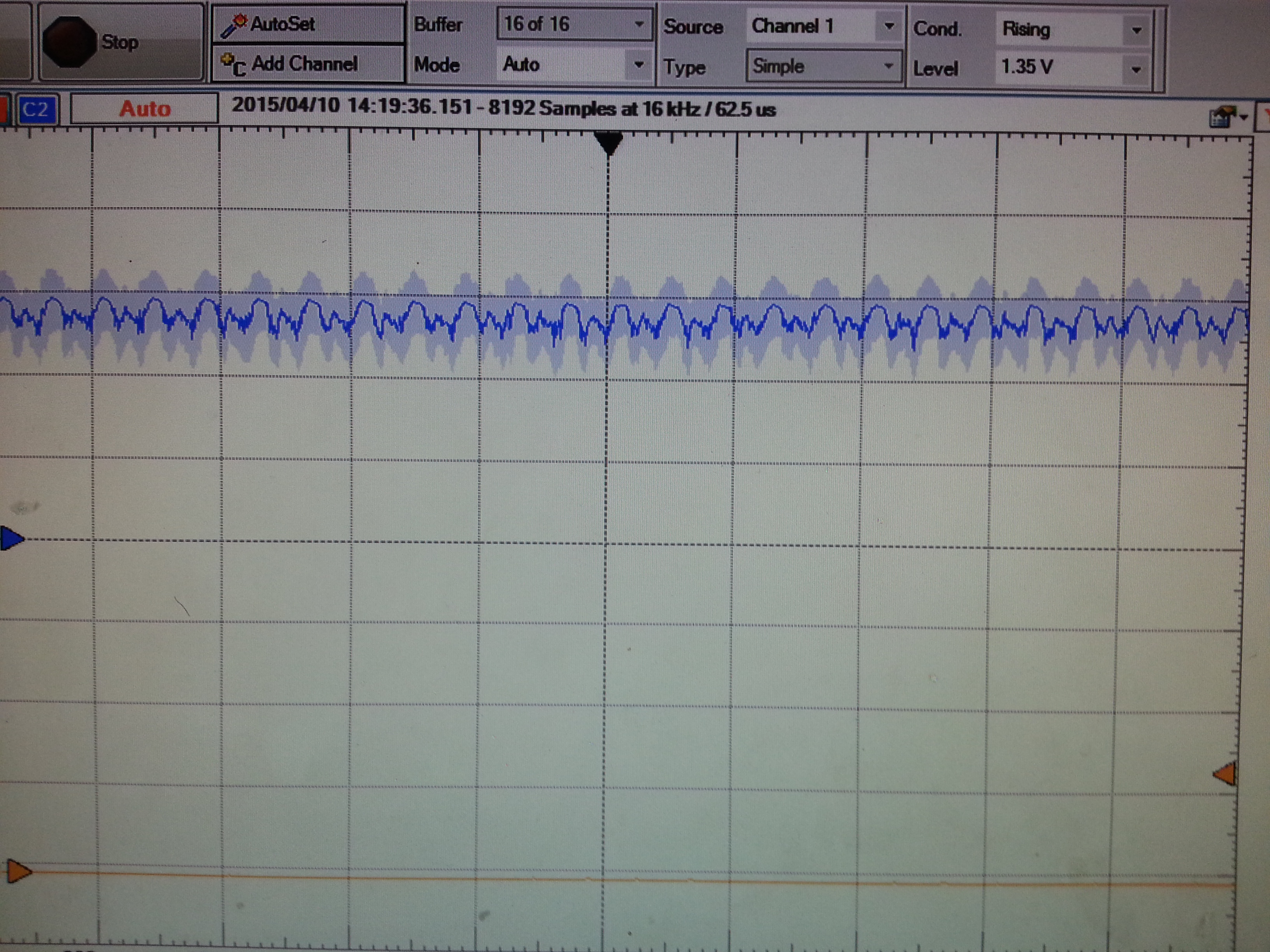
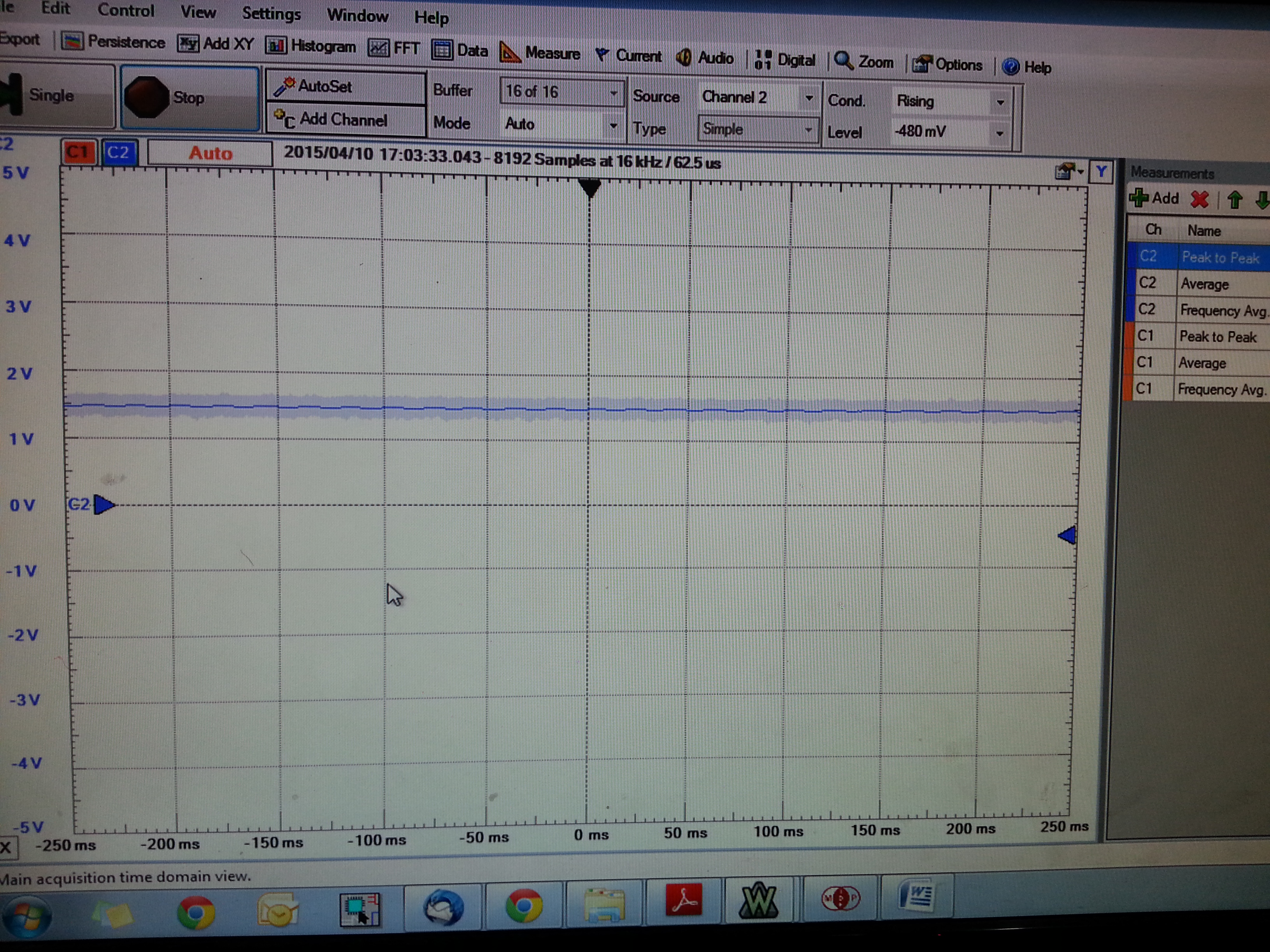
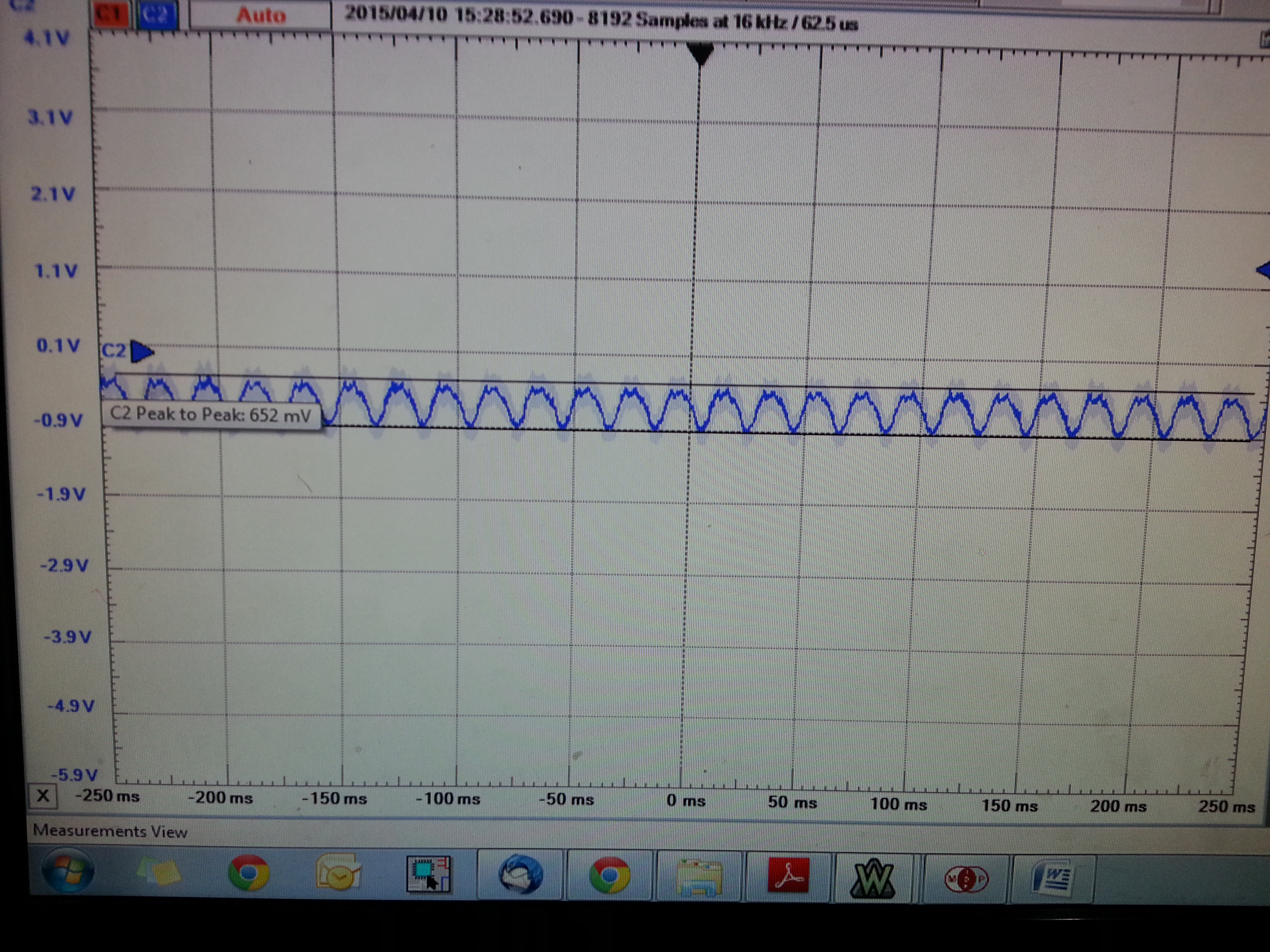
This is my output in MPIDE software

on
---------------------------------------------------------
sent: 0x020
recieved: 0x073
-- ID115-----------------------------------------------------------
sent: 0x0B 0x00 0
---------------------------------------------------------
CONFIGs 1 2
---------------------------------------------------------
sent: 0x01 0x02 10
---------------------------------------------------------
sent: 0x02 0x0A0 10100000
---------------------------------------------------------
Check Configs
---------------------------------------------------------
sent: 0x01
recieved: 0x02
CONFIG1: 2 0x02
---------------------------------------------------------
sent: 0x02
recieved: 0x0A0
CONFIG2: 160 0x0A0
---------------------------------------------------------
Set Channels
---------------------------------------------------------
sent: 0x04 0x020 100000
---------------------------------------------------------
sent: 0x04 0x00 0
---------------------------------------------------------
sent: 0x04 0x00 0
---------------------------------------------------------
sent: 0x05 0x020 100000
---------------------------------------------------------
sent: 0x05 0x00 0
---------------------------------------------------------
sent: 0x05 0x00 0
---------------------------------------------------------
detecting active channels:
---------------------------------------------------------
sent: 0x04
recieved: 0x00
1: 0 0x00
---------------------------------------------------------
sent: 0x05
recieved: 0x00as
2: 0 0x00
detected 2 active channels.
off
on
---------------------------------------------------------
sent: 0x020
recieved: 0x073
-- ID115-----------------------------------------------------------
sent: 0x0B 0x00 0
---------------------------------------------------------
CONFIGs 1 2
---------------------------------------------------------
sent: 0x01 0x02 10
---------------------------------------------------------
sent: 0x02 0x0A0 10100000
---------------------------------------------------------
Check Configs
---------------------------------------------------------
sent: 0x01
recieved: 0x02
CONFIG1: 2 0x02
---------------------------------------------------------
sent: 0x02
recieved: 0x0A0
CONFIG2: 160 0x0A0
---------------------------------------------------------
Set Channels
---------------------------------------------------------
sent: 0x04 0x020 100000
---------------------------------------------------------
sent: 0x04 0x00 0
---------------------------------------------------------
sent: 0x04 0x00 0
---------------------------------------------------------
sent: 0x05 0x020 100000
---------------------------------------------------------
sent: 0x05 0x00 0
---------------------------------------------------------
sent: 0x05 0x00 0
---------------------------------------------------------
detecting active channels:
---------------------------------------------------------
sent: 0x04
recieved: 0x00
1: 0 0x00
---------------------------------------------------------
sent: 0x05
recieved: 0x00
2: 0 0x00
detected 2 active channels.
off
ID bits are set to 0x73
Config1 =0x02
Config2= 0xA0 but actually i tried for 0xA8..its not coming in output
Loff=0x00 //bcoz my aim is to obtain only respiratory wave continuously
Ch1 and Ch2= 0x00
RLD and Loff sense=0x00
Loff stat and Gpio=0x00
REsp1=0xCA//22 deg phase
Resp2=0x03
The problem with above program is attached my circuit
  1.   Whether my program and output is correct?
  2.   I set config 2 for A8 but iam getting A0 in output shown above
  3. iam getting waveforms only when switch is pressed but i have written in program for RDATAC continuous mode. Please reply me how can i change my program so that i get respiration output continuously???
  4. whether this chip gives only digital output?? how can i change this output to analog and view my respiration waveform continuosly using LABVIEW DAQ?? what should i do for it in addition??
  5. How many electrodes i need to use for it?? and where i should place the electrodes??
  6. From which pin i need to take output??

waiting for response


Thanks in advanceecg_schematic.pdf2.pdf


  • Hello Srividhyasakthi,

    I can try my best to answer your questions one by one.

    1. I’d like to clarify the purpose of this forum as it relates to review of code. If you have a specific problem with the code as it relates to SPI configuration or program flow, then we would be happy to take a look at it and provide you with as much guidance as we are qualified to give. Such a problem should be stated with as much detail as possible and have as little to do with to the controller architecture or platform as possible.
    2. If you are debugging any SPI communication problem, I would recommend you start by looking at the SPI pins with an oscilloscope and making sure the transaction looks as you expect.
    3. I’m not sure to which switch you are referring. There weren’t any on your schematic. In addition, your RESP_MOD pins are not connected in a way that will allow respiration measurement, so I wouldn’t trust the data that you are receiving as valid respiration data.
    4. It’s possible to take the PGA output signals from the PGAxP/N pins. The output from those PGA pins will be the input signal gained by the PGA gain. If you were to configure your hardware for respiration measurement, you could look at the demodulated respiration signal using those pins.
    5. Does this question refer to looking at the signals you are acquiring before they are converted to digital? In that case, refer to my answer to question 4.
    6. Does this question also refer to looking at the signals in the analog domain before they are converted? If that is the case, refer again to answer 4.

    Regards,

    Brian Pisani

  • Thanks Mr Brian Pisani added following circuit with previous schematic in order to get respiratory wave 

    op.pdf

    AVDD=+1.5V

    AVCC=-1.5V

    DVDD=+3.3V

    DVCC=ground

    got following output

    1. output between PGA1P and PGA1N

    when electrodes held in hand

    when connected across PGA2P and PGA2N got following output

    by connecting right arm and left arm electrodes

      across PGA1 getting 400MV by connecting electrode getting 700MV

    similarly across PGA2 getting MV signal by connecting electrodes 1v

    1. not getting correct ECG wave and Respiratory wave??
    2. whether above wave is noise or iam getting correct output??
    3. whether i must add amplifier and filter circuitfurther to get correct wave in LABVIEW DAQ??
    4. If yes please send me the circuit??


  • Hello Srividhyasakthi,
    It's hard for me to tell if you are getting any of the correct waveforms. The signals that you are showing me have a fundamental frequency of around 50 Hz which is probably the utility frequency in your region. You should try to make your inputs as free of noise as possible. In addition, an ECG amplitude could be as little as a few millivolts so you'll have to decrease your volts/div on the scope to see that. The respiration signal will also be a few millivolts and probably have a frequency of less than 1 Hz so it's important that you can protect your measurement lines from noise.

    I'm not sure how you'd measure that signal using a LabVIEW DAQ and unfortunately I do not believe we have one for the specific setup you are describing.

    Regards,
    Brian Pisani
  • Sir, I am also working on the project of measuring ECG signals from ads1292r using Procentral ads1292r devlopment kit. The good thing is Procentral has provided the libraries on the github for Arduino and then using SPI communication i want to retrive ECG data from the ads1292r. but the provided program is bit confusing and i really dont know to to get ECG data from which particular Registers of ads1292r so i need help regarding that...