This thread has been locked.

If you have a related question, please click the "Ask a related question" button in the top right corner. The newly created question will be automatically linked to this question.

ADS1198 Right Arm leads-off status only when LOFF_FLIP=0x00.

Other Parts Discussed in Thread: ADS1198, ADS1298, ADS1194

Hello all,

My previous post got blocked by moderator and the link doesn't seem to open.

So, i am re-posting my question.

I have configured the ADS1198 to acquire ECG.

Whenever i configure LOFF_FLIP (Address = 11h) value to 0xFF, i get lead-off status correctly for all leads except Right Arm lead.

And when i configure LOFF_FLIP=0x00, i get lead-off status for Right Arm lead, but not other leads.

Can anyone please tell me what the problem might be ??

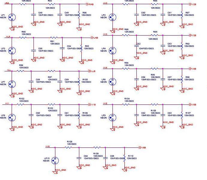
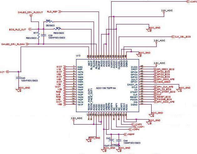
I am sharing the ADS1198 connection diagram.

Warm regards,

Abhishek.

  • Hello all,

    I am sharing my leads-connection diagram.

    Regards,

    Abhishek.

  • Hi Abhishek,

    I believe the reason that lead-off detection works for most of the leads when LOFF_FLIP = 0xFF and only the RA lead when LOFF_FLIP = 0x00 is because the RA lead is the only lead connected to a negative input and you are using pull-down resistors for all inputs. When LOFF_FLIP = 0xFF, positive inputs will trigger a lead-off detection when their voltage gets too low. The lead-off current source is sinking current from the input to AVSS. That means that when the lead is off on the positive inputs, the current flowing through the pull-down resistor will cause the voltage to go very low triggering a detection. For the RA lead, the current source is sourcing current from AVDD and the comparator is looking for the voltage to get too high. However your pull-down resistor is keeping the voltage there low enough to never trigger a detection.

    When LOFF_FLIP = 0x00, the opposite is true. The comparators for the positive inputs will only trigger when the voltage gets too high, but the pull-down is keeping it low, and the comparator for the RA lead is easily triggering at the low voltage when the lead is off. To remedy this, I would recommend simply removing all of the 10 MOhm pull-down resistors and setting LOFF_FLIP to 0x00. That way when the lead comes off, the current sources will just saturate the channel in the correct direction which will trigger the right detection every time.

    Regards,
    Brian Pisani
  • Hello Brian,
    Thank you very much for detailed explanation.
    I implemented your remedy.

    I am getting leads-off for all leads now. But the leads-off status is updated about 20 seconds after the leads is actually disconnected(which is too long).


    Also, along with LOFF_FLIP = 0x00, should i make changes to any other configuration registers also ??

    Please reply.
    Warm regards,
    Abhishek.

  • Hi Abhishek,

    I know how you have your LOFF_SENS and LOFF_FLIP registers configured, but what are currently the contents of your LOFF and CONFIG4 registers? Also, how are you detecting a lead off event? Are you reading the status bytes that are output with the conversion data or are you polling the LOFF_STAT registers?

    Regards,
    Brian Pisani
  • Hello Brian,

    Thank you for replying.

    The current contents of my LOFF and CONFIG4 registers are:-

    LOFF: Lead-Off Control Register (Address = 04h) = 0x0B.

    RLD_SENSP (Address = 0Dh) = 0x06.

    RLD_SENSN (Address = 0Eh) = 0x06.

    LOFF_SENSP (Address = 0Fh) = 0xFF.

    LOFF_SENSN (Address = 10h) = 0x06.

    LOFF_FLIP (Address = 11h) = 0xFF.

    CONFIG4: Configuration Register 4 (Address = 17h) = 0x02.

    Yes, i am detecting the lead-off event by reading the status bytes that are output with conversion data i.e. 1100 + LOFF_STATP + LOFF_STATN + bits[4:7].

    I am not polling the LOFF_STAT registers.

    Warm regards,

    Abhishek.

  • Hi Abhishek,

    Have you tried changing your comparator threshold level settings? Right now you are at the most stringent threshold. Try making bits [7:5] of the LOFF register 001 or even 010 and see what happens.

    Brian Pisani
  • Hello Brian,

    Please let me brief you about the recent settings that are working.

    I have removed the R86(10Mohm) resistor of RA lead and not removed 10Mohm resistors of other leads(see diagram).

    And, with the above configuration register settings, i am getting leads-off for all leads except that the leads-off for RA leads is detected after about 20 seconds or so.

    But, i cannot find and logical explanation to that.

    I will implement your advice about changing the comparator threshold level settings and get back with the results.

    Thanks and regards,

    Abhishek.

  • Hello Brian,
    I checked all values of the comparator threshold level settings, but it doesn't have any effect on the leads-off.
    The RA lead-off status is detected only after sometime.

    Also, when i put the R86(10Mohm) resistor back, i don't get RA lead-off status even after sometime.

    Awaiting your reply.

    Thanks and regards,
    Abhishek.
  • Hey Abhishek,

    Looking more carefully at your schematic, the path for the input doesn't terminate at the connector. What is located to the left of all of those connectors? I fear that by taking off the resistors you may have reduced the impedance to ground versus making it infinite. Also, have you tried doing lead-off detection using the internal pull-up/down resistors as opposed to the current source lead-off detection?

    Regards,
    Brian Pisani
  • Hello Brian,

    The components on the left of all those connectors are EPCOS Surge Arrestors. They are used to remove any surge in the circuit.

    Right now, we have not connected these Surge Arrestors in our circuit.

    So you mean that the R86(10Mohm) resistance is necessary and should be connected in the circuit ??

    Yes, we had tried the pull-up/down resistor mode, but that didn't work. So we switched to current source mode for leads-off detection.

    Thanks and regards,

    Abhishek.

  • Abhishek,

    Given how we expect the device to work, none of the external pull down resistors should be necessary. If there was no path to ground and the electrode net was just floating which would be the case when the lead is off, no current can flow on that net since the circuit is open. You would expect that the lead-off current source would then saturate the channel and trigger the lead-off comparator. Does that make sense?

    One thing we can try is perhaps probing the voltage on the input pins between the time you pull the lead off and when the lead-off detection is triggered. We should expect it to drop immediately to a low voltage for the positive inputs and a high voltage for your RA input pins since your LOFF_FLIP register is set to 0xFF. If for some reason it doesn't change right away, then something must not be happening as we expect.

    Regards,
    Brian Pisani
  • Hello Brian,

    Yes, you are right with the first part.

    Your very first remedy was to eliminate all the pull-down resistors, which i had implemented then.

    The result was that the leads-off status was generated after very long time after the lead was physically disconnected (about 20-30 seconds).

    Hence i put back the pull-down resistors.

    I will probe the voltage on the input puns as you suggest and get back with the results.

    Thanks and regards,

    Abhishek.

  • Hello Brian,
    There's been a lot of trial-and-error for this issue.
    Can you please suggest me the ideal conditions which give us correct leads-off for all channels viz. CONFIG and other register settings, lead connections to ADS1198 etc ??
    So that i can implement the ideal connections and check my circuit.

    Thanks and regards,
    Abhishek.
  • Hey Abhishek,

    For DC lead off detection, leads should not be AC coupled and should be connected to the input pins of the ADS1298. No pull-up or pull-down resistors should be necessary. Electrode traces can and ideally should be connected such that there is no other path for DC current to flow on the trace except from the input pins to the electrode and vice versa.

    LOFF register: 0x0F   // Current source DC lead off with a current magnitude of 24 nA (note: first three bits set the comparator threshold and need not be equal to b000) 

    LOFF_SENSP register: 0xFF 

    LOFF_SENSN register: 0x06 // Only activate lead-off for negative inputs 2 and 3 since the others are connected to the WCT amp and will never trigger a detection 

    LOFF_FLIP register: 0x00  // If there are no pull-up/down resistors, either direction should work 

    CONFIG4 register:0x02 // Turn on the lead-off comparators by setting bit 1; other settings are application dependent 

    If you can confirm that these are your settings and lead-off detection still does not work right away, then I would still try probing the input pins and see what happens to the voltages when you physically disconnect the electrodes.

    Regards,

    Brian Pisani

  • Hello Brian,

    Thank you very much for replying.

    I will remove the RC components between the leads and ADS1198 pins, set the register values and check for leads-off.

    I will get back with the results.

    Warm regards,

    Abhishek.

  • Hello Brian,
    One thing is that the leads-off don't work when LOFF_FLIP register: 0x00.
    We only get RA and RL leads-off status when LOFF_FLIP register: 0x00.

    I am working on eliminating the RC components and checking leads-off.
    Will get back.

    Thanks and regards,
    Abhishek.

  • Hello Brian,
    I removed all the RC components for all leads between lead and ADS1198 pin.
    But now, i am not getting leads-off for any lead !!

    Regards,
    Abhishek.
  • Hey Abhishek,

    Is the conversion data you are receiving indicate that the channel is saturated? For instance with the positive leads, if the channel was saturating to the positive voltage you would expect the data to be near full-scale positive.

    Brian Pisani
  • Hello Brian,

    I viewed the lead voltages on the DSO:-

    All leads(LA, RL, LL and V1 to V6) show 1.5V when connected and ~20mV when disconnected, and give leads-off detection in conversion data.

    But, RA shows 1.5V when connected and ~141mV when disconnected and doesn't give lead-off detection in conversion data !!


    Warm regards,

    Abhishek.

  • Hi Abhishek,

    Am I correct in saying that in the case you specified with the RA lead that the pin is truly in an open circuit state (i.e. no pull-up/down resistors, no protection diodes that may leak)? Are those measured voltages with respect to AVSS?

    Regards,
    Brian Pisani
  • Hello Brian,
    I checked the voltages on DSO for both conditions i.e. when the filters and pull-down resistors are connected, and disconnected.

    The above case is when the filters and pull-down resistors are connected.

    Yes, i measured those voltages with respect to AVss(ADS1198 pin no.23).

    Thanks and regards,
    Abhishek.
  • Abhishek,

    My fear is that the measured voltage on the RA trace is not railing because current is leaking somewhere in your passive network on that trace. Is it possible to unpopulate all of those components on the RA trace and then measure the voltage on the input just for this test? If it still does not rail, then it would eliminate the possibility of current leaking by some of your passive components.

    Regards,
    Brian Pisani
  • Hello Brian,

    Thank you for replying !!

    Yes, i will implement your advice and remove all passive components between RA lead and ADS1198 and check the voltages.

    But, i have prepared about 10 prototype boards using the ADS1198, and all seem to have the same problem!!

    I could attribute the current leak for components in some boards, but how can all have the same problem ??

    Thanks and regards,

    Abhishek.

  • Abhishek,

    You saying that gives me confidence that it is a board issue since I've seen plenty of examples on the forum of lead-off detection working perfectly for all leads as I'm sure you have as well. This is good news since once we figure out what is causing it, we can work to fix it!

    Let me clarify what I mean when I say that a component is leaking current. It's not to say that the component is faulty or not performing to specification, it just means that it is draining current where you do not expect. The lead-off detection current sources source a small amount of current (on the order of nanoamps). If there was a protection diode or some other component in the path of the lead that on its datasheet is said to consume some small quantity of current when in an "off" state (perhaps also on the order of nanoamperes), then it might prevent the lead-off current source from saturating the comparator. This would tend to happen for all of your boards since presumably you use the same components for all your boards.

    Let me know what you find.

    Regards,

    Brian Pisani

  • Hello Brian,

    Thank you very much for replying.

    I will check-out with different boards and see what happens in leads-off condition.

    Hopefully, we will sort this issue now.

    Will post the results here and let you know.

    Regards,

    Abhishek.

  • Hello Abhishek,

    Sounds good. Let me know what you find!

    Regards,
    Brian Pisani
  • Hello Brian,

    Testing with one prototype and coming to a conclusion is incorrect from my side.

    So, i am making 5 more prototypes and testing them with different conditions (i.e. connecting/disconnecting passive components etc). It would take me a week or so to get back with results.

    Will post the results here.

    Thanks and regards,

    Abhishek.

  • Hello Brian,

    I am still struggling with this leads-off issue.

    I made 20 prototypes to eliminate the possibility of testing on a faulty circuit board.

    But i am still unable to get leads-off for RA lead on any of the boards.

    Btw, i also connected ADS1194 instead of ADS1198 to see if the issue still persists, and even ADS1194 doesn't give leads-off for RA lead.

    How should i solve this now ??

    Regards,

    Abhishek.

  • Hey Abhishek,

    There must be a component leaking current. You can determine this by probing your resistors and seeing if any voltage is being dropped across them and remove components incrementally and see where the problem stops happening.

    Regards,
    Brian Pisani
  • Hi Brian,

    I probed the voltages on the leads. For all other leads, upon leads-off, the voltages fall below 30mV and i get leads-off status correctly.

    But only for RA lead, the voltage falls to about 50mV.

    Moreover, i have connected the same components for all the leads, so why is only RA not indicating leads-off. ??

    Regards,

    Abhishek.

  • Hey Abhishek,

    The lead-off circuitry has pretty wide tolerance since it was not designed for precision. One strategy would be for you to tighten the comparator threshold in the LOFF register such that it will trigger at a higher voltage.

    Brian
  • Hi Brian,
    I changed the comparator thresholds to 70%-30% and also changed the Lead-off current magnitudes between 4nA to 16nA.
    But i am still not getting RA leads-off.

    Regards,
    Abhishek.
  • Hey Abhishek,

    Can you tell me what voltages you measure across the passive components in the path of the RA electrodes?

    Brian
  • Hi Brian,
    I am getting the following voltages across the passive components of RA lead.
    1.49V when lead is connected and 136mV when lead is disconnected.
    These voltages are across R86, C49 and C48.

    Regards,
    Abhishek.
  • Hey Abhishek,

    Have your tried depopulating those pull-down resistors? If you depopulate R86 and preform lead-off detection in current source mode it should work.

    Brian Pisani
  • Hi Brian,

    Yes, i got leads-off when i depopulated the R86 resistor !!

    But why this happens with RA lead only, and not with other leads ??

    I still have the 10Mohm resistors connected to rest of the leads, and they detect leads-off correctly.

    Regards,

    Abhishek.

  • Hey Abhishek,

    This is because the RA electrode is connected to a negative channel input whereas all the others are connected to positive channel inputs. A good way to think about it would be to draw a schematic and create current sources of the magnitude and direction specified by your register settings and calculate the ideal voltages that appear at the inputs in the case where the electrode is off.

    Regards,
    Brian Pisani
  • Hi Brian,
    Thank you so much.
    I understood it now.

    Best regards,
    Abhishek.