This thread has been locked.

If you have a related question, please click the "Ask a related question" button in the top right corner. The newly created question will be automatically linked to this question.

How to use ADS1191/ADS1192 and ADS1x9xECG-FE

Other Parts Discussed in Thread: ADS1192, ADS1191

I have 4 questions about ADS1191/ADS1192 and ADS1x9xECG-FE

1.)How should we connect to IN2P and IN2N of ADS1191(ADC 1ch)?

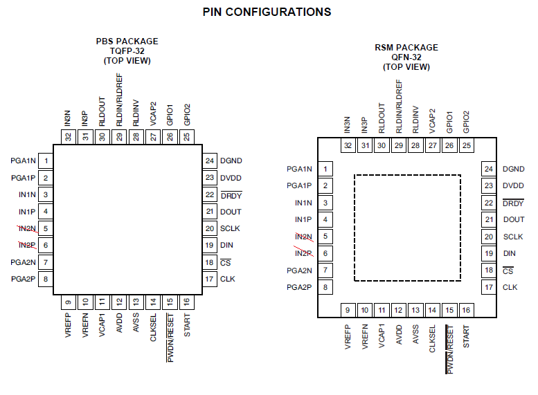
   Customer wants to use ADS1191(ADC 1ch).    Datasheet page9 and 10 describe 'PIN CONFIGURATIONS' and 'PIN ASSIGNMENTS'.    It seems for ADS1192(ADC 2ch), because these have IN2P and IN2N(ADC Chennel2).    Do you have 'PIN CONFIGURATIONS' and 'PIN ASSIGNMENTS' for ADS1191(ADC 1ch)?       If ADS1191 and ADS1192 are same 'PIN CONFIGURATIONS' and 'PIN ASSIGNMENTS',    How should we set for IN2P and IN2N of ADS1191? Non-connection(N/C) or GND?   

2.) Datasheet Error about CLK_EN bit of ADS1191/ADS1192.

Datasheet page24 shows following.

The CLKSEL pin selects either the internal or external clock. The CLK_EN bit in the CONFIG1 register enables and disables the oscillator clock to be output in the CLK pin

But CONFIG1 register doesn't include CLK_EN. Page36 'Table 8. Register Assignments' shows that CLK_EN is in CONFIG2 register. I think that CLK_EN of CONFIG2 is correct.

【ADS1191/ADS1192 Datasheet】

www.tij.co.jp/.../ads1191.pdf

3.)'Lead Off Status' for ADS1x9xECG-FE Software

The table of page 27 shows 'Lead Off Status'. What's the meaning of the status during blinking?

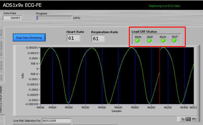
4.)Lead Off Status for RL

The table of page 40 shows 4 Leads(RA、LA、LL、RL), but figure of page 27 doesn't include 'RL off' on 'Leads'. Is this correct? or error of UserGuide?

【ADS1x9xECG-FE UserGuide】

www.tij.co.jp/.../slau384a.pdf

  • Hello y.i,

    1. On the ADS1191, you should short the channel 2 inputs together. No need to tie them to ground.
    2. Thank you for pointing this out. It is a known typo and will be fixed in the next revision of the datasheet. The register map section can be trusted to have the right assignments.
    3. Do they blink during data acquisition? Those lights indicate if the leads are still connected to the body, but the correct register configurations must be made to ensure the correct operation.
    4. That is not a typo. The RL electrode plays a special role in biopotential measurements. That electrode typically does not measure any signals. It instead injects a known voltage on to the body to stabilize the common mode drift of the other electrodes. RL lead-off detection can be performed on this device, but it is done in a different way than the channel electrodes. I would advise reading page 50 of the datasheet for information about RLD lead-off detection.

    Regards,
    Brian Pisani
  • Hello Brian,

    Thank you for your reply.
    I insert my comment to your answer.

    1. I undersand that IN2P and IN2N should short together for channel 2 of ADS1191.
    Thank you.

    2. I understand. Thanks.

    3. Unfortunately I don't have enough information about blinking.
    I ask the customer for that again, especially when the lights are blinking.

    4. I understand. Thanks.

    Best Reagards,
    y.i
  • Hello Brian,

    Thank you for your answer.

    Our customer would like to know the detail about question No1.

    Could you recheck following 3 questions?

    a.) I think that datasheet describes 'PIN CONFIGURATIONS' and 'PIN ASSIGNMENTS' based on only ADS1192(Not ADS1191).

       May I understand that pins of ADS1191 are the same 'PIN CONFIGURATIONS' and 'PIN ASSIGNMENTS' except IN2P and IN2N ?

    b.) Do you have a plan to describe 'PIN CONFIGURATIONS' and 'PIN ASSIGNMENTS' of ADS1191 on datasheet ?

    c.) Could you explain why should we deal with following about IN2P and IN2N?

       Are these IN2P and IN2N connected to circuit such as ADC inside chip of ADS1191?

       (IN2P and IN2N are not N/C pin for ADS1191 ?)

     >On the ADS1191, you should short the channel 2 inputs together. No need to tie them to ground.

    Best Reagards,

    y.i

  • Hello y.i,

    a. Yes the pin configurations and pin assignments are exactly the same from the ADS1191 to the ADS1192 with the exception of the channel 2 input pins on the ADS1192, which are to be shorted together, and the PGA2N and PGA2P output pins, which may be left floating. This device only has one channel, but the pinout is exactly the same as the two-channel device. You can expect functionality to be nearly the same as the two channel version.

    b. At this time no, but I could foresee some more descriptive language in the existing PIN CONFIGURATIONS and PIN ASSIGNMENTS sections about how to deal with the unused pins on the ADS1191 make its way into the next revision. Thanks for your feedback on that!

    c. To see maximum power performance, it is advised that you short those pins.

    Regards,
    Brian Pisani