This thread has been locked.

If you have a related question, please click the "Ask a related question" button in the top right corner. The newly created question will be automatically linked to this question.

AFE4490 ADC_RDY Issue, Getting Three interrupt pulses

Other Parts Discussed in Thread: AFE4490

Hello,

           I am trying to implement pulse oximeter using AFE4490 with MSP430, I can configure the AFE4490 through SPI and can able to read the register outputs. My question is, The AFE_ADC_RDY is not running in the same frequency of PRP(500 Hz). We were getting three pulses in the ADC_RDY signal, What could be the problem.. Is this normal activity or are we doing any mistake in hardware design and AFE4490 internal register configuration. Kindly check the attached image.

CH 1:  SCLK

CH 2:  MOSI

CH 3: MISO

CH 4: ADC_RDY

  • Hello Praba,

    We have received your enquiry about AFE4490 and will get back to you with a response soon.
  • Praba,

    This looks more like a scope capture issue.
    Could you remove the SPI signals on other channels and trigger the capture on ADC_RDY signal?
  • Hello,
    I have the same issue. I am seeing three pulses at a time and that is all, whether I check it while the front-end software is capturing samples, or whether I use my own board (after removing the concerning 0 ohm resistors) to send data via SPI (and I have used the default register values given in the source code).
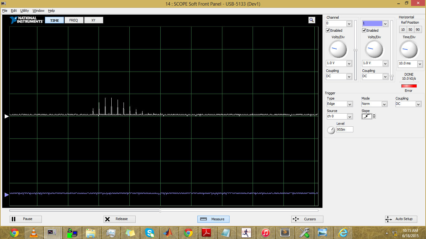
    The three pulses themselves differ by 2ms, when I keep the sampling rate as 500 Hz, and by 0.5 ms when I set the sampling rate as 2kHz (and when I set it as 2kHz, there is a similar bunching of ADC_RDY signals, but more than three - around 7 pulses). There is only one signal scoped out, and I am using a National Instruments USB DAQ to scope out the results.

    Additionally, you had, in another post, described the conditions for not seeing ADC_RDY:

    1. device is in hardware reset (AFE_RESETZ pin low)
    2. device is in software reset (SW_RST bit set)
    3. device in hardware powerdown (AFE_PDNZ pin low)
    4. device in software powerdown (PDNAFE bit set)
    5. when the Pulse Repetition count (PRPCT) is not set
    6. When the TIMEREN bit is not set
    7. When the correct clock mode is not set (XTAL_DISABLE bit)

    Accordingly, I am confirming that when I use my own board with SPI:

    1. AFE_RESETZ is pulled high
    2. SW_RST was first set and then reset.
    3. AFE_PDNZ pulled high
    4. PDNAFE bit is not set
    5. PRPCT is set (to 7999)
    6. TIMEREN bit is set
    7. XTALDIS: Crystal disable mode

    0 = The crystal module is enabled; the 8-MHz crystal must be connected to the XIN and
    XOUT pins
    1 = The crystal module is disabled; an external 8-MHz clock must be applied to the XIN pin
    This bit is 0. (Do I have to do anything additional in hardware or software to connect XTAL to XIN and XOUT?)

    Moreover, the Photodiode is also lighting up when I use my own board.
    I took readings from SPI interface and plotted the results in MATLAB. 

    Here the ppg waveform shape is visible  - but there are a lot of spikes (noise?). Could it have something to do with the ADC not being ready to sample data?
    These are 9900 samples of data.

    Any idea as to why I am unable to see regular ADC_RDY pulses? This prevents me from using it as an interrupt to read data.

    Regards,
    Samyukta

  • Samyukta,

    Can you send us a screen shot of your ADC_RDY captured on a scope in the different variations that you described?
  • Hi,

          Those three ADC_RDY pulses are related to scope capturing. We were getting that sort of signals while capturing large amount of signals. Keep your scope capturing resolution is low.. you wont get that issue.

  • Hello Amy,

    1) 500 Hz sampling = 6 spikes fitting exactly in 10ms period  gives a period of 2 ms. 

    I used a resistor of 420 ohms to pullup AFE_RESET and AFE_PDNZ.

    2) 2kHz sampling rate: 20 pulses in 10ms = 0.5 ms period

    In general, I see variations when I change the pullup for the AFE_RESETZ and AFE_PDNZ. Is there any specific value and configuration that should be there?

    Regards,

    Samyukta

  • Hello,
    How low should I keep the resolution? Because I have been able to see 16khz pulses accurately on the NI DAQ that I am using, so I am wondering why 500 Hz should be an issue..
    Also, the spikes that you got and that I got are slightly different. Mine are fading into zero, as you can see in the screenshot.
    Any further suggestions would be most welcome.
    Regards,
    Samyukta
  • Hello,
    Any further suggestions / resolution for this issue?
    Regards,
    Samyukta