This thread has been locked.

If you have a related question, please click the "Ask a related question" button in the top right corner. The newly created question will be automatically linked to this question.

CDCE62005 setting issue on DAC3482EVM

Other Parts Discussed in Thread: CDCE62005

Hi,

I'm testing DAC3482EVM with TSW1400.

It is working fine with external clock input, but it is looked like the output clock was not correct frequency when I tried to use on-board CDCE620005 clock generator.

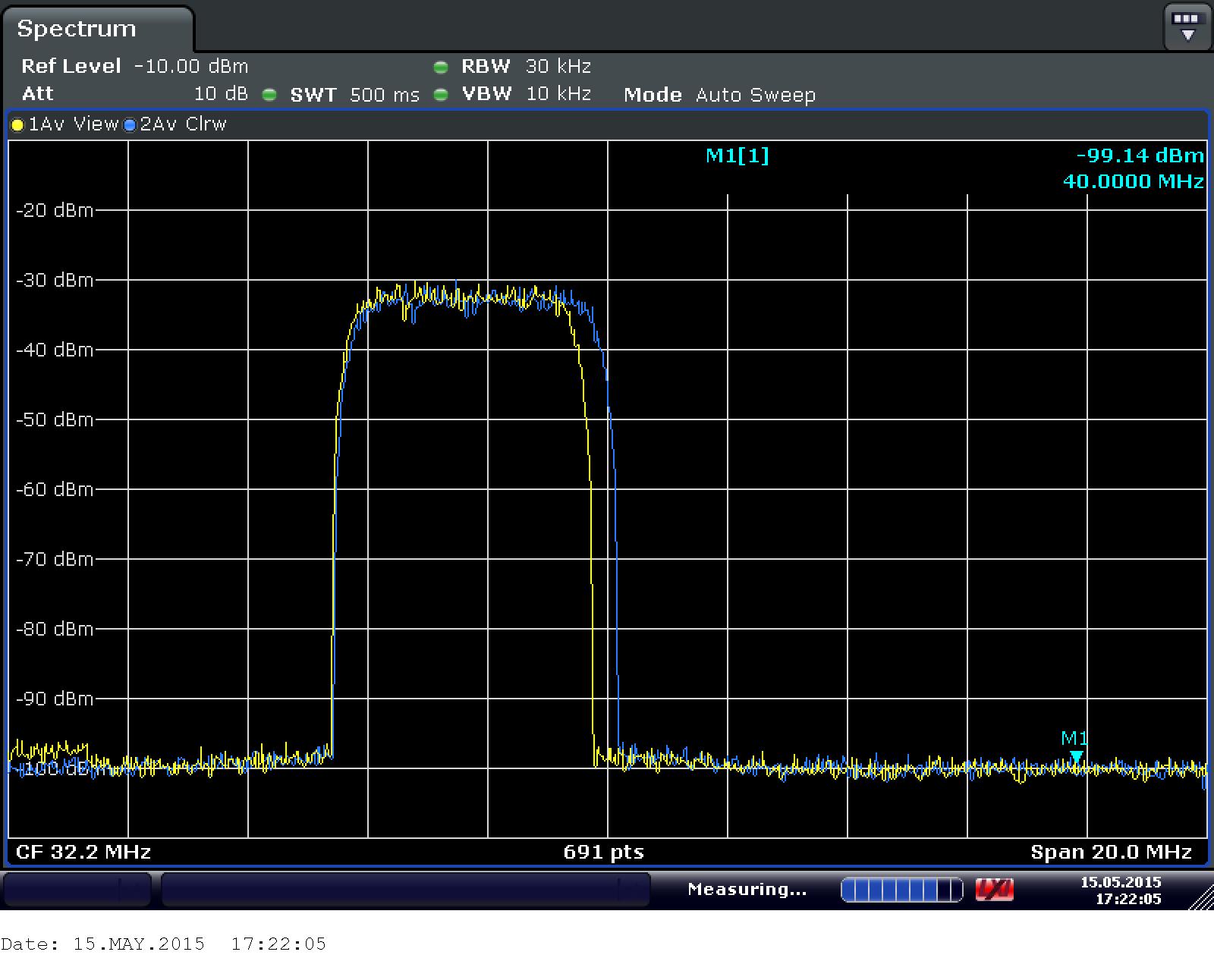
The screen capture in below shows the test result. Blue colored trace is when external clock used which is working well.

Yellow one is when CDCE62005 VCO is used. In case of yellow trace, center frequency is shifted about 1.25MHz to left and bandwidth of the trace is narrow comparing with normal case.

The register I used is as following.

-------

 x00    xF18C
   x01    x0000
   x02    x8052
   x03    xA001
   x04    xFFFF
   x05    x0460
   x06    x2900
   x07    xFFFF
   x08    x0000
   x09    x8000
   x0A    x0000
   x0B    x0000
   x0C    x05A6
   x0D    x05A6
   x0E    x05A6
   x0F    x05A6
   x10    x3000
   x11    x0000
   x12    x0000
   x13    x0000
   x14    x0000
   x15    x0000
   x16    x0000
   x17    x1900
   x18    x205F
   x19    x10F4
   x1A    x4820
   x1B    x0800
   x1C    x0000
   x1D    x0000
   x1E    x1111
   x1F    x8882
   x20    x2400
   x22    x1B1B
   x23    x001F
   x24    x1000
   x25    x7A7A
   x26    xB6B6
   x27    xEAEA
   x28    x4545
   x29    x1A1A
   x2A    x1616
   x2B    xAAAA
   x2C    xC6C6
   x2D    x0004
   x2E    x0000
   x2F    x0000
   x30    x61A8
   x7F    x0004
CDCE62005 Registers
Freq:19.200000MHz
Address Data
00  80400000
01  811C0321
02  81400302
03  81040303
04  00040304
05  00101A85
06  04BF0FA6
07  151877F7
08  20001C08

------

I assumed that 19.2MHz TCXO output is fed to Secondary reference input, and expected Fout from Synthesize of CDCE62005 was 614.4MHz.

Thank you very much for your help in advance!

Y.K.Choi

  • Hi Y.K.Choi,

    I will replicate the same setup with the register settings you have provided. When the CDCE62005 PLL is locked, led D1 should turn on. Can you confirm this on your EVM? Can you also confirm with an Oscilloscope, the sampling clock frequency at the DACCLKP/N pins?

    Thanks,

    Eben.

  • Hi Eben,

    Thank you very much for your prompt answer!

    LED D1 was not turned on when I applied the settings.

    It seems like Loop Filter setting was not proper.

    I don't have Oscilloscope so I couldn't check out the clock output.

    Y.K.Choi

  • Hi, Eben,

    It was so glad to meet you in IMS2015 exhibition last week in Pheonix.

    Now, I'm writing my own signal creation and editing application using Visual Studio C++ and VB.net.
    And, I want to embed control code for TSW1400EVM and DAC3482EVM which is running without opening of "High Speed Data Converter Pro GUI".

    I could find out DLL and header file such as "TSW1400Board_CLib.dll", "TSW1400_API.h" and so on in following file path:
    C:\Program Files\Texas Instruments\High Speed Data Converter Pro\1400 Details\

    Also, there is document, "TSW1400_software_API.doc" to explain software API.

    However, there is no manual or example code that show me how to use the API.

    So, it would be very helpful if you provide me either VB.net or Visual Studio C++ exmaple code that show me how to use the API with which library files.

    Thank you very much for your support in advance!

    Y.K.Choi
  • Further TSW1400EVM DLL and API discussions can be found in the following post:
    e2e.ti.com/.../1525020
  • Hi YK,

    Also share your email address so I can share some source files which may be relevant to you. It was nice to meet you at IMS.

    Thanks,
    Eben.
  • Hi! Eben,

    My email address is:
    ykchoi@cnk-tek.com

    Thank you and have a good weekend!

    Y.K.Choi