Hi All,
working on ADS7830 driver IC for ADC conversion.
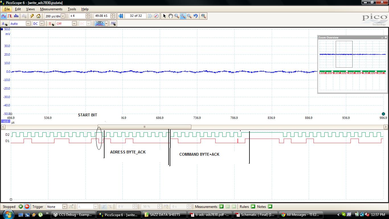
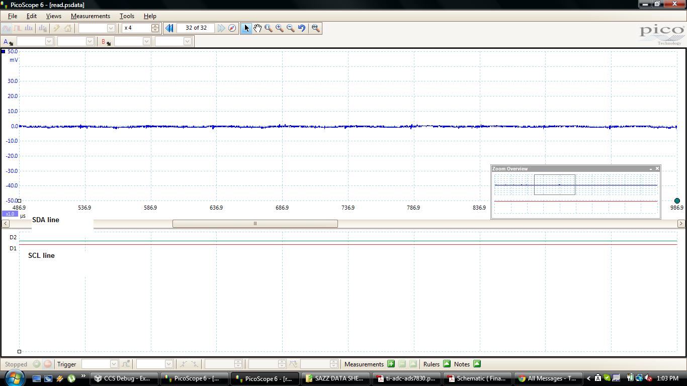
Using F28069 controller and I2C speed is standard mode(100KHz) , Only I2C write is working fine, getting ACK from ADS7830 but write andReading is not working always SDA is LOW(3.3v) and SCL HIGH(0V).
1.my slave Address is 0x48, means (According to Data sheet of ADS7830) The first five bits(MSBs) of the slave address are factory pre-set to 10010.The next two bits of the address byte are the device select bits, A1 and A0. Input pins (A1-A0) on the ADS7830 determine these two bits of the device address for a particular ADS7830.
Both A0 & A1 are grounded in my hardware.
2. Command BYTE value is 0x8C means Single ended I/P is High and POWER DOWN selection, Both PD1 and PD0 are high means Internal Reference ON and A/D Converter ON.
attaching what ever capture in writing and reading time. and also attaching code.
please help me to solve this problem.
void main(void)
{
// Uint16 Error;
// Uint16 i,j=0,a=0;
// CurrentMsgPtr = &I2cMsgOut1;
// Step 1. Initialize System Control:
// PLL, WatchDog, enable Peripheral Clocks
// This example function is found in the F2806x_SysCtrl.c file.
InitSysCtrl();
// Step 2. Initalize GPIO:
// This example function is found in the F2806x_Gpio.c file and
// illustrates how to set the GPIO to it's default state.
// InitGpio();
// Setup only the GP I/O only for I2C functionality
InitI2CGpio();
// Step 3. Clear all interrupts and initialize PIE vector table:
// Disable CPU interrupts
DINT;
// Initialize PIE control registers to their default state.
// The default state is all PIE interrupts disabled and flags
// are cleared.
// This function is found in the F2806x_PieCtrl.c file.
InitPieCtrl();
// Disable CPU interrupts and clear all CPU interrupt flags:
IER = 0x0000;
IFR = 0x0000;
// Initialize the PIE vector table with pointers to the shell Interrupt
// Service Routines (ISR).
// This will populate the entire table, even if the interrupt
// is not used in this example. This is useful for debug purposes.
// The shell ISR routines are found in F2806x_DefaultIsr.c.
// This function is found in F2806x_PieVect.c.
InitPieVectTable();
// Interrupts that are used in this example are re-mapped to
// ISR functions found within this file.
EALLOW; // This is needed to write to EALLOW protected registers
PieVectTable.I2CINT1A = &i2c_int1a_isr;
EDIS; // This is needed to disable write to EALLOW protected registers
// Step 4. Initialize all the Device Peripherals:
// This function is found in F2806x_InitPeripherals.c
// InitPeripherals(); // Not required for this example
I2CA_Init();
// Enable interrupts required for this example
// Enable I2C interrupt 1 in the PIE: Group 8 interrupt 1
PieCtrlRegs.PIEIER8.bit.INTx1 = 1;
// Enable CPU INT8 which is connected to PIE group 8
IER |= M_INT8;
EINT;
for(;;)
{
I2caRegs.I2CDRR=0x00;
Write();
Read();
I2caRegs.I2CMDR.bit.STP = 1;
} // end of for(;;)
} // end of main
__interrupt void i2c_int1a_isr(void)
{
if(c_store==2)
{
c_store=0;
}
Serial_I2c=I2caRegs.I2CDRR;
I2c_rx[c_store]=Serial_I2c;
c_store++;
PieCtrlRegs.PIEACK.all = PIEACK_GROUP8;
}
void I2CA_Init(void)
{
I2caRegs.I2CPSC.all = 8; // Prescaler - need 7-12 Mhz on module clk
I2caRegs.I2CCLKL = 45; // NOTE: must be non zero
I2caRegs.I2CCLKH = 45; // NOTE: must be non zero
I2caRegs.I2CIER.all = 0x24; // Enable SCD & ARDY interrupts
I2caRegs.I2CMDR.all = 0x0020; // Take I2C out of reset
// Stop I2C when suspended
I2caRegs.I2CMDR.bit.STB |=1;
// I2caRegs.I2CFFTX.all = 0x6000; // Enable FIFO mode and TXFIFO
//I2caRegs.I2CFFRX.all = 0x2070;//0x2040; // Enable RXFIFO, clear RXFFINT,
I2caRegs.I2CSTR.bit.RRDY = 1; // Clear flag
I2caRegs.I2CIER.bit.RRDY = 1; // Enable Receive Interrupt
return;
}
void Write()
{
Uint16 cj=0;
I2caRegs.I2CDXR = 0x8C; //config reg.selection
I2c_Master_TX_mode_CH0(1,I2C_SLAVE_ADDR);
for(cj=0;cj<300;cj++); //217 microsec.
}
void Read()
{
I2caRegs.I2CDXR = 0x8C;
I2c_Master_Rx(1,I2C_SLAVE_ADDR);
Parameters();
}
void I2c_Master_TX_mode_CH0(Uint16 Nbits,Uint16 Sadd)
{
I2caRegs.I2CCNT = Nbits;
while(I2caRegs.I2CSTR.bit.BB!=1) //checking i2c bus is free or not
{
I2caRegs.I2CMDR.bit.MST = 1;
I2caRegs.I2CMDR.bit.STT = 1;
I2caRegs.I2CMDR.bit.TRX = 1;
I2caRegs.I2CSAR = Sadd;
I2caRegs.I2CMDR.bit.FREE = 1;
I2caRegs.I2CMDR.bit.STP = 1;
}
}
void I2c_Master_Rx(Uint16 Nbits,Uint16 Sadd)
{
I2caRegs.I2CCNT = Nbits;
while(I2caRegs.I2CSTR.bit.BB!=1) //checking i2c bus is free or not
{
I2caRegs.I2CMDR.bit.MST = 1;
I2caRegs.I2CMDR.bit.STT = 1;
I2caRegs.I2CMDR.bit.TRX = 1;
I2caRegs.I2CSAR = Sadd;
I2caRegs.I2CMDR.bit.FREE = 1;
I2caRegs.I2CMDR.bit.STP = 1;
// I2caRegs.I2CMDR.bit.RM = 1;
}
}
void Parameters()
{
I2caRegs.I2CCNT =1;
I2caRegs.I2CMDR.bit.STT = 1; //Repeated start, Reception will follow
I2caRegs.I2CMDR.bit.MST = 1; //Set to Master mode
I2caRegs.I2CMDR.bit.TRX = 0; //Set to Recieve mode
I2caRegs.I2CMDR.bit.FREE = 1; //Run in FREE mode
I2caRegs.I2CMDR.bit.NACKMOD=1;
I2caRegs.I2CMDR.bit.STP = 0; //Stop when internal counter becomes 0
}