This thread has been locked.

If you have a related question, please click the "Ask a related question" button in the top right corner. The newly created question will be automatically linked to this question.

ADS1299EEG-FE Biasing

Other Parts Discussed in Thread: ADS1299

Hello,

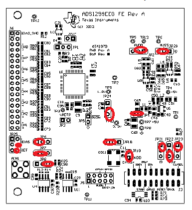
I'm a student and fairly new to this. I am under the impression that with JP6 configured as 1-2 this outputs a mid-supply voltage to BIAS_ELEC, which can be accessed on JP25 pin 4 and applied to the patient. I measured the voltage from this pin to the board's ground via a test point and read 0 Volts. It also appears to not be doing anything when I try to read single-ended inputs (which I am using the same set-up except for inputs on the channel's + pins. What am I doing wrong? Should I be sending this signal to the ADS1299 (BIASIN) instead and biasing with the output? I thought that was just another method if you'd like to set your own bias point? 

Register settings are default. At this point, I just want to be able to get a bias out. When doing single-ended, I've been working with one channel and applying input to the +, and common reference through SRB1. I also noticed when I leave the inputs as open, with nothing attached, each channel has some weird bias around 0.48 V (PGA gain =1) when JP25[3-4,5-6] are connected. Is this the mid-supply? If so, it seems awfully low? I tested the voltages at each test point, and it looks good.

Thank you,

Meagan

  • Hi Meagan,

    First, I'm required to tell you that the EVM to be used in a laboratory environment for evaluation purposes only. The EVM should not be used as any part of end equipment nor should it be used with live test subjects.

    The goal of the bias electrode is to stabilize the common mode of all the inputs to some known voltage since, without some sort of active source driving the patient, the voltages are prone to wide common mode drifts. You've mentioned that your measurement electrodes are connected to the positive input pins, but what is connected to the negative inputs? Or instead do you have something driving a reference electrode which is in turn connected to the SRB1 pin? One potential strategy to measure signals in a single ended configuration would be to both drive the bias electrode and feed the output of U11 to the SRB1 pin to use that as a common signal reference for all the measurement electrodes.

    While you are correct that U11 is installed to give you flexibility with what common mode you establish for your inputs, if R23 and R24 are not changed, the output voltage will always be mid-supply. Also keep in mind that the ADS1299 has an on-chip BIAS amplifier which will essentially perform the same task as U11 or provide even better common mode rejection, depending on how you use it.

    Regarding your question about the voltage on the floating pins, I do not believe you are measuring the bias voltage established by the bias electrode since there is no conductive path between the two . If they are floating, their voltage will be undetermined and measuring it provides no useful information.

    Regards,
    Brian Pisani
  • Hi Brian,

    I still have a lot of confusion regarding this.

    In general:
    When I turn on the bias buffer, the GUI auto-sets BIASSENSP to 0x06 and BIASSENSN to 0x0E. Why? If I change these settings if i'd like a channel to have a driving bias, what does that imply for those pre-set settings? I just don't see a reason for them to be set... When I deselect them, I can't ever seem to deselect BIASSENSN.

    For the Test Signal Amplitude: (VREFP-VREFN)/2.4 and generated internally set,DC, all channels set to "Test Signal", PGA Gain = 1, I get something at 0.24 mV, when I set the PGA gain = 24, I'll get the correct amplitude.

    For actual measurement test I'm trying to do:

    I'm trying to use the Bias Measurement option to read the mid-supply when JP6[2-3], routing 2.5V to PGAP (I'm using Channel1). BIASREF_INT = 1. I keep getting 2.48V (Gain = 1) for this measurement. Shouldn't I be getting something extremely small close to 0 because it's 2.5V measured with respect to 2.5V (since I'm using a unipolar supply AVDD+AVSS/2)? I'm correct in assuming i don't need to enable the bias buffer? To simply see what the voltage BIASIN relative to BIASREF?

    My register settings are attached. The only difference in my jumper settings from my previous post is that there is nothing on Channel inputs and JP6 is now 2-3 (routing mid supply to BIASIN). What am I missing?

    CONFIG1 = 0x93
    CONFIG2= 0xD3
    CONFIG3 = 0xF8
    CH1SET = 0x02

    Additionally, can you elaborate what the Input referred option means.

    Thank you. Sorry this is a lot of questions.

    Meagan

  • EDIT: I realized I didn't have my bias buffer enabled. But when I enable it, I'm able to make correct measurements. Why should this matter? Isn't BIASIN routed to the channel regardless if the buffer is on or not? Or is it due to the internal BIASREF? Regardless, I thought these didn't need to be routed through the buffer when simply being hooked up to the channels?
  • Hey Meagan,

    If you look at figure 46 of the ADS1299 datasheet, you will see a very helpful diagram of the BIASIN measurement functionality. As you can see, BIASIN is routed from the output of the amplifier in through the BIASIN pin. That indicates that the BIAS amplifier must be powered on in order to measure the correct voltage.

    As for the BIAS_SENS register defaults when the EVM turns on, I am unsure why that is the case, though I do not doubt it. When the ADS1299 powers up, both registers are set to 0x00. If you would like to know more about how the BIAS_SENS registers work on this device, figure 52 in the ADS1299 datasheet essentially summarizes the functionality.

    Regards,
    Brian Pisani