


Hello there,
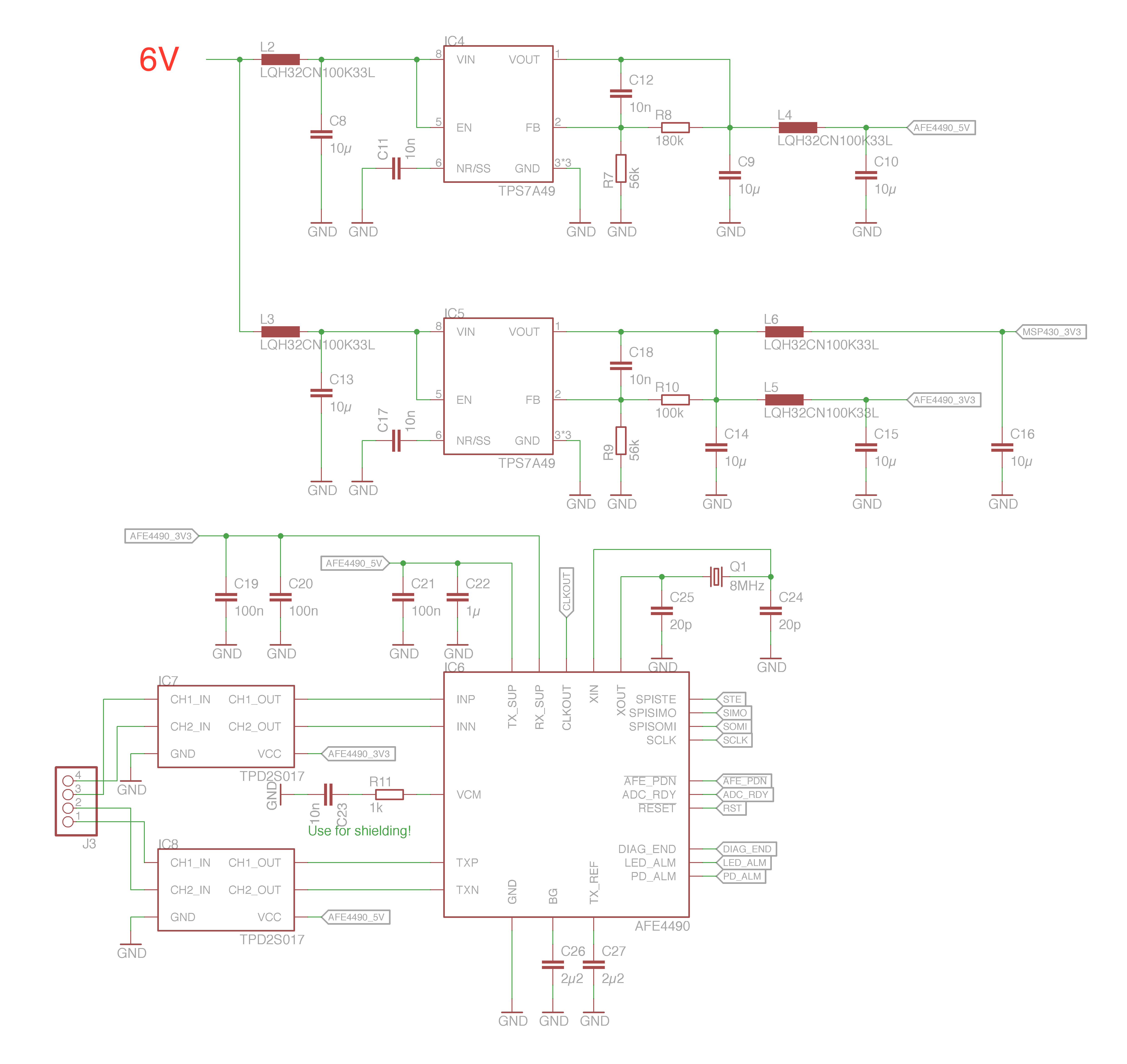
i have build a custom PCB for PPG measurement with the TI AFE4490. It has been designed with respect to all recommendations of the datasheet.
Tx supply is 5V and Rx supply is 3V3. Osrams SFH7050 is used for red/infrared light source and reflection measurement.
But i have two problems:
1. I am not able to see any pulse on the ADC_RDY pin. It seems to be the same problem as in this thread: 
I have double checked that all possible reasons for the signal to be not generated are not true in my case. Besides, the 3State Option is not used. Because i want to check if the other components are working as expected, i have used the option to brought the internal period of LED2 convert to the PD_ALM pin (CLKALMPIN in CONTROL1 register, p. 72). On every rising edge on PD_ALM, i then read out the values of the conversion.
2. With the PD_ALM-workaround for synchronization, i have another problem with the measured signal. When placing the thumb on the SFH7050, the signal seems to go to a kind of saturation very early. The LED1 channel voltage has a maximum of ~33mV, LED2 channel of ~22mV. Changing Rf and Rg has no effect other then reaching the 'saturation level' faster or slower. In the short GIF i prepared you can see the placing and releasing of my thumb and the resulting limitation of the measured signal:
I am assuming that the TIA and/or stage 2 amplifier are malfunctioning. The reason for this assumption is the fact that i can measure voltages of 80mV in ADC_Bypass mode, when the amplifiers are decoupled. I think that this 80mV is a kind of floating drift voltage indicating no limiting malfunction of the ADC itself.
Regards


