Other Parts Discussed in Thread: ADS1299
I have EEG Front-End Performance Demonstration Kit and got clear idea bout the operation of the chip.
Then I decided to use ADS1299EEG-FE Daughter Card separately with Arduino DUE.
Then I made all the necessary connections(SPI , Reset, Start, DRDY) between Daughter Card and Arduino. The required power (3.3V and 5V , GND) are supplied from Arduino board.
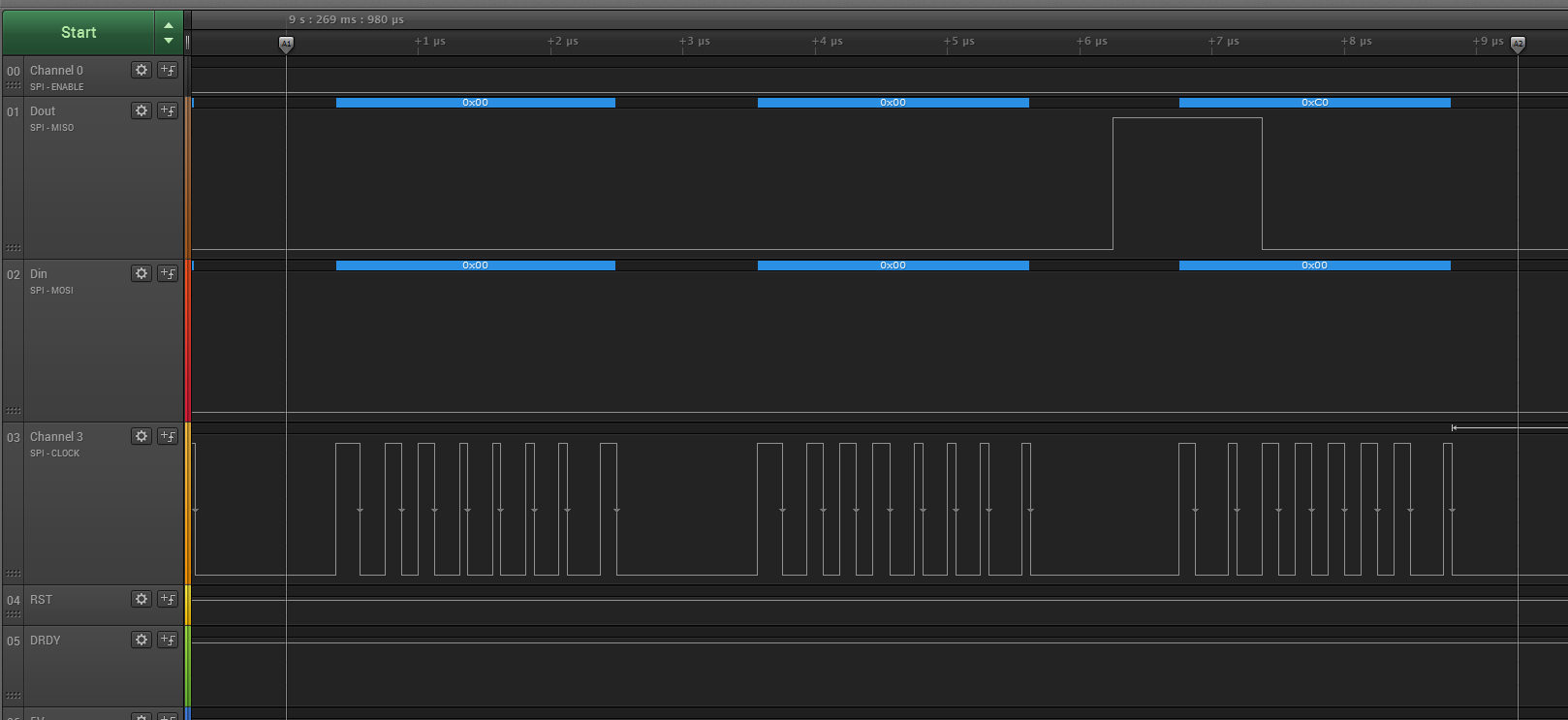
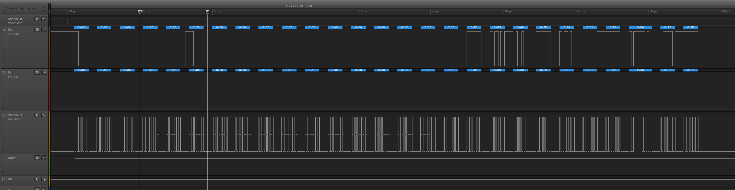
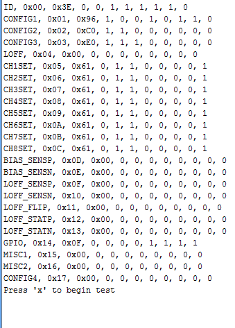
When I run the program it shows the default register values correctly as follows. That implies the chip powered up correctly
Then I Modified CONFIG3, CONFIG1, CH1SET registers to apply TEST signal to CH1 and take 250 samples.
Case 1 : START pin is connected with CS pin using JP22 of the Daughter Card
The problems comes after this.
- It takes 4026 ms to take 250 samples. This is unusual time since the default sampling rate = 250 SPS. Then I assume the sampling rate is less than 250SPS
- When I plot the graph I do not show the square wave pattern as I expected.(I think due to low sample Rate)

Then I apply Small Sine signal externally To CH1 from a signal generator. ( Vpp= 10 mV , f=6 Hz)
This signal show on the graph correctly. But when the frequency of the signal increases above 10 Hz, the graph start to distorted .
Case 2 : START pin is directly connected to GND
- At this time It take only 1322 ms to take 250 samples which is a reasonable time . But the problem is I don’t observe the correct Square wave form from the channel.


The waveform is in this graphs but there are un expected peak values (errors) ..
Sometimes the graph shows almost correct with small level of error values as follows


According to the manual START pin should be grounded
Please help me to correct this. I think I’m almost done but stuck at this point.