This thread has been locked.

If you have a related question, please click the "Ask a related question" button in the top right corner. The newly created question will be automatically linked to this question.

ADS1292R wrong ECG

Other Parts Discussed in Thread: ADS1292R, ADS1292

Hi.  I had configured ADS1292R to generate the test signal and have displayed square wave at 1 Hz, so communication with  the microcontroller is correct. I try to measure ECG  using only 2 leads without RLD out lead, but a get wrong data.

My ADS1292R configuration is: 

ads1292_Reg_Write(ADS1292_REG_CONFIG1, 0x00);

ads1292_Reg_Write(ADS1292_REG_CONFIG2, 0xA0);

ads1292_Reg_Write(ADS1292_REG_LOFF, 0x10);

ads1292_Reg_Write(ADS1292_REG_CH1SET, 0x80);  

ads1292_Reg_Write(ADS1292_REG_CH2SET, 0x40);

ads1292_Reg_Write(ADS1292_REG_RLDSENS, 0x00);

ads1292_Reg_Write(ADS1292_REG_LOFFSENS, 0x00);

ads1292_Reg_Write(ADS1292_REG_RESP1, 0x00);

ads1292_Reg_Write(ADS1292_REG_RESP2, 0x00);  

ads1292_Reg_Read(ADS1292_REG_RESP2, 0x00);  

I'm confused, can anyone help me?

Regards,

Victor

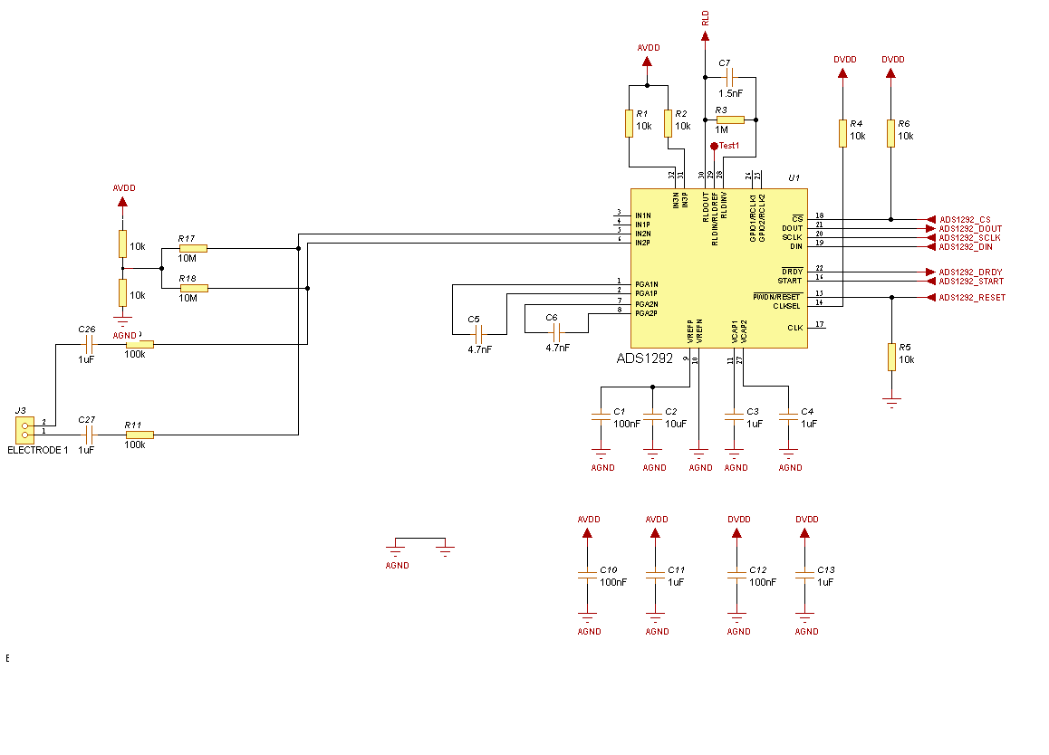
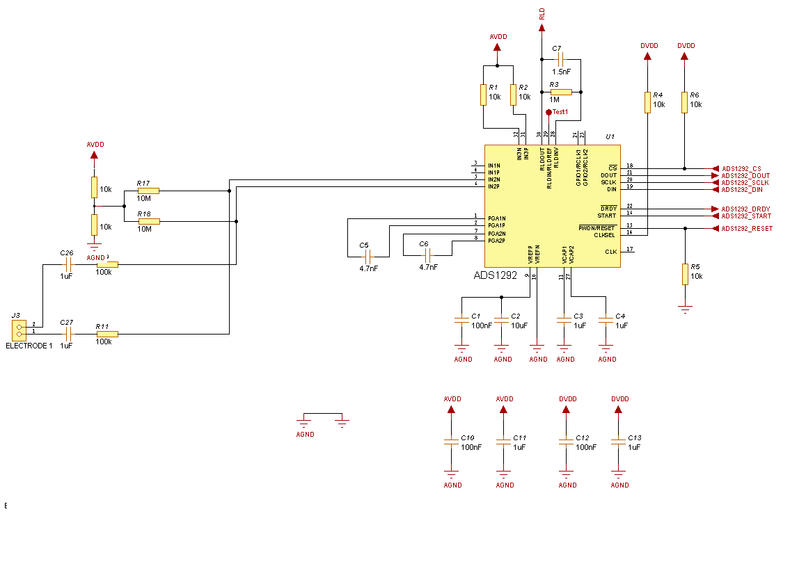
  • Sorry, but in  the previous post, I have added incorrect schematic. Below is correct:

  • Hey Victor,

    Can you pleas be more specific with what you mean when you say you are getting the wrong data? Is it just noise? If that is the case, one issue I can see is that you have no anti-aliasing filter on the inputs. In order to prevent wide-band noise from entering the converter, it is critical that the input band be limited roughly to the frequency range where you expect the signal to be. The digital filter on this device will repeat its response centered around integer multiples of the modulator frequency.

    I'd also recommend setting bit 2 of the RESP1 register and bit 1 of the RESP2 register since the datasheet specifies that those bits must always be set to 1. I'm not sure exactly what would happen if they were cleared, but just to be safe, I'd recommend always keeping them set.

    Regards,
    Brian Pisani
  • I set  bit 2 of the RESP1 register and bit 1 of the RESP2 but it doesn't help.

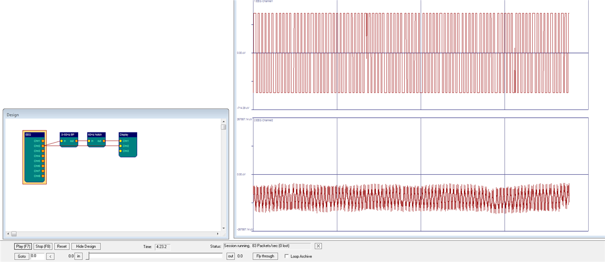
    My ECG is:

    What I can check  to fixed it?

    Thanks in advance!

  • Hey Victor,

    From the data you are receiving, it looks as though the device is converting correctly and you are reading correctly. That leaves just a few things that could be preventing you from reading the data. First, the lack of an anti-aliasing filter at the input will cause out of band noise to have a presence at the output. Most notably, this will take place at integer multiples of the sampling frequency since the ADS1292's digital filter frequency response will repeat at those intervals. Try blue wiring in shunt capacitors after the resistors at the input (that will form an RC filter) with the correct time constant to pass your band through the filter.

    In addition, it seems as though your software processes the data through a couple of filters. What are those filter coefficients? I'd check to make sure they are not unexpectedly taking out some of your passband.

    Regards,
    Brian Pisani
  • Thanks ! Ok, I will add anti-aliasing filter.
    In screen:
    1. After filter. First filter is bandpass butterworth 0.5-50Hz 8 order, after second notch filter 59-61 Hz 8 order. I tried different filter, but it didn't help.
    2. Raw data.
    It seems to me that I must see raw ECG without program filters or not ?
    Could you check my ADS1292R configuration is right for the current schematic ?
  • Hey Victor,

    The schematic and settings looks fine. Have you tried using a signal generator to see if you could see a simple sine wave at the output?

    Brian
  • If I understood you correctly, I must connect a signal generator to input of ADS1292R and see simple sine wave , yes ?
  • Hey Victor,

    Put it across your board inputs (J3) since the inputs are AC coupled. Given that the waveform is in the passband of your filters, you should be able to see a sine wave in that scenario.

    Regards,
    Brian Pisani