Because of the holidays, TI E2E™ design support forum responses will be delayed from Dec. 25 through Jan. 2. Thank you for your patience.

This thread has been locked.

If you have a related question, please click the "Ask a related question" button in the top right corner. The newly created question will be automatically linked to this question.

How to construct DB15 cable suggested in Appendix B of ADS1298ECG-FE PDK User Manual?

Other Parts Discussed in Thread: ADS1298

Hi,

Could you give me some advice on how I would construct the DB15 cable suggested in the ADS1298ECG-FE PDK User Manual?

I have a DB15 serial cable already. I am just not sure how to go from 15 pins to 10 leads; which are not used? Also, for the ones that are used, how do 10 leads correspond to 8 channels and would I be able to get a differential signal input in this way?

Thanks so much

-David 


  • Hey David,

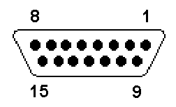
    I found this pinout for a male DB-15 connector searching the web. This should correspond to the pinout of the connector on the EVM board. If not, try mirroring it:

    DB15 diagram

    As for the question of which leads correspond to which pins and how they ultimately connect to the device, I'd advise taking a look at the board schematic near the end of the user's guide for the EVM. It will show all the electrical connections from the connector into the device. Feel free to post again if you have any more questions.

    Regards,

    Brian Pisani

  • Hi Brian,

    Thanks for the quick response!

    I plan to use the ADS1298 for EMG. Would you suggest I don't use the serial port then and just connect leads directly to the jumpers?

    Thanks!

  • Hey David,

    The EVM board is constructed to be convenient for ECG measurement. If you look at how the electrodes ultimately get connected to the channels, they are paired off by the different ECG lead vectors. I'm not as familiar with EMG measurement, but what I can say is that it will be better to use the connector since the RC low-pass anti-aliasing filters occur on the path from the connector to the jumper. If you were to connect electrodes directly to the jumpers, you would be bypassing those critical components.

    Regards,
    Brian Pisani
  • Got it, okay. And where would I connect ELEC_SHD to? I know ELEC_V1-6, RA,LA,LL,RL all correspond to electrodes.
    Would I connect ELEC_SHD to the shielding of the serial cable?

    Also, I assume these would be single-ended inputs?

    Thanks!
  • Hey David,

    You are correct; ELEC_SHD is to be connected to the cable shield. If you do not have a shield for your cable for test purposes, you can leave that pin disconnected.

    The inputs on this device will be measured differentially. Refer to pages 55-57 of the ADS1298 datasheet for a discussion on the inputs and their range.

    Regards,
    Brian Pisani
  • Awesome! Thanks again for the prompt response.

    In reference to what are the inputs from the serial cable measured deferentially? Some kind of internal reference voltage?

    When connecting leads directly to jumpers (one to + and one to -) it makes sense to me which two signals are subtracted. It's not too clear to me what is the case when sending inputs through the serial cable.

    Thanks again

    -David

  • David,

    Look at the channel 2 inputs to the device as an example. The output corresponding to channel 2 will be measured as the voltages IN2P - IN2N. If you were to short pins 1 and 2 and pins 3 and 4 of JP32, the signal would come from the cable. As you can tell from the labels on the schematic this cable inputs correspond to the LA and RA ECG leads. The output of channel 2 will then correspond to LA - RA which is the Lead I ECG vector. In fact all of the inputs for this EVM are designed to be one ECG lead vector or another. If you were to short JP16, the voltage output from the on-chip Wilson Central terminal amplifier will be present at those pins.

    They are set up to easily measure ECG signals, but ultimately, they are just wires that connect to a simple differential votlage measuring ADC. You can connect practically any voltages to the lines (according tot he device datasheet, of course) and they will be converted to digital codes - it doesn't have to be ECG.

    Regards,
    Brian Pisani