This thread has been locked.

If you have a related question, please click the "Ask a related question" button in the top right corner. The newly created question will be automatically linked to this question.

ads1191 electrodes design and RLD

Other Parts Discussed in Thread: ADS1191, ADS1192

currently, i am designing a medical device using ads1191.  And i confronted some problems about the electrodes design. 

1. what is the RLD signal used for? I heard about that RLD ia able to improve common mode rejection, and how should i design the RLD circuit to achieve this? In this forum, i found some experts mentioned that "using 10M series resistors to tie the RLD signal to the current electrodes to set the operating point or use some sort of resistor pull up/down network to bias the input accordingly". 

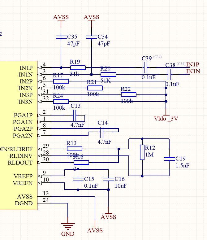
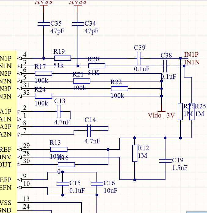
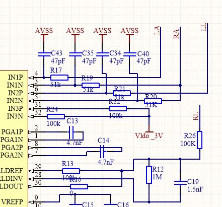
 this is part of my schematic. please check it whether the RLD circuit is correct.

  • Hey Xin,

    Both of the things you've heard are correct. In general, the RLD amplifier on this device is used to maintain the input common mode within the valid measurement range for the device by connecting the output to the patient drive electrode. For information on how this affects common mode rejection, refer to this application note: www.ti.com/.../sbaa188.pdf

    Using the RLD output to bias the input is typically done in ac coupled systems where a patient drive electrode is not used. There must be some way of maintaining the input within the valid measurement range, so a series capacitor is placed on the inputs and a pull-up resistor is placed between the RLDOUT pin and the inputs to bias them at mid-supply.

    Your RLD component configuration looks good. If you are unsure how the components will effect the system, take a look at Figure 47 of the ADS1191 datasheet. It provides an equivalent circuit diagram for the RLD amplifier and a few external components. For analyzing the circuit, treat the RLD amplifier like any op-amp you studied in school (i.e. infinite open-loop gain, virtual ground between the inputs, zero input current).

    Regards,
    Brian Pisani
  • HI, Brian

    Thank you very much. So According to your answer,in order to using the RLD output to bias the input,  I need to connect the output of RLDOUT pin to the input channel, right?

    this is the modified schematic, please check it 

  • Hey Xin,

    The RLDOUT connections should be placed after C38 and C39 rather than before. After you have placed the connections correctly, be conscious of the values you use for R25 and R26. Consider that in the small signal model for the circuit, the RLDOUT pin is AC ground. Then C39 and R26 form an RC high-pass filter to the input (similarly for R25 and C38). If you maintain the 1 MOhm resistor, the corner frequency of that filter will be 1/(2*pi*R*C) = 1.6 Hz. You may be attenuating some of your ECG signal with such a high cutoff! If you make that resistor larger, you can reduce that cutoff frequency.

    Also, since you are just using the RLD amplifier as a simple buffer, you can short out R12 and C19 since they govern the frequency response of the amplifier in the case where the RLD amplifier is used to drive the RL electrode.

    Regards,
    Brian Pisani
  • Hi Brian

    Thanks very much for your advice.
    what i understand is that R19 and C35 is a RC low pass filter and c39 ,R26 is the high pass filter to AC-coupled the input signal , in addition RLDOUT is act as DC bias to achieve mid-supply,is it right?
    since in this case, i hardly use three electrodes(RA,LA,RL), without using RLD electrode, is it still possible to improve common mode rejection based on my circuit?
  • Hey Xin,

    Your understanding of the passive components is correct. You can't improve common mode rejection using the Right Leg Drive amplifier as suggested in the application note I linked to earlier because you are not using a RL electrode. The RLD output is simply used to bias the inputs in this case and provides no common mode rejection.

    Regards,
    Brian Pisani
  • Hi Brian

    Thank you so much.

    in order to improve common mode rejection, i need connect the RLDOUT pin to a electrode ,right? However  if i connect RLDOUT to a  electrode rather than short with inputs, should i design some circuit to bias the inputs?

    since my Prof need me design 2-channel device now,  so normally how to arrange the input channel,  can I set IN1P, IN1N,IN2P,IN2N as RA,LA,RL,LL respectively? 

    and if i set like that , how about RLD electrode?  

  • Hey Xin,

    You will not be able to bias it with AVSS since that would violate equation 3 in the ADS1191 datasheet, but you could instead install a voltage divider between AVDD and AVSS to bias the inputs to analog mid-supply. However, if you're going to bias the patient with the RL electrode, you likely do not need to AC couple the inputs because the RLD amplifier will do the work of maintain the inputs withing the valid common-mode range.

    Unfortunately the ADS1191 is a 1 channel device so you will not be able to do 2 channel conversion with this part. You should look into the ADS1192, which is the same package as the ADS1191 but has an additional delta-sigma modulator. In that case, you can simply connect your additional lead to IN2P and IN2N.

    Regards,
    Brian Pisani
  • HI Brain

    Thank you for your excellent  prompt.

    actually, I am a year-3 EE undergraduate student , and I am not very familiar with ECG knowledge. if i use 2-channel ads1192. how should i arrange the 4 inputs? must the RLDOUT pin be connected with RL electrode? or could I connect the IN1P ,IN1N,IN2P,IN2N to RA,LA,LL,RL electrode respectively?   so sorry, my expression may be a little bit confused.

  • Hey Xin,

    The RL electrode is not a measurement electrode and is tied to the RLDOUT pin as a patient drive electrode. It's goal is to keep the voltage of the body at a constant potential relative to the board supplies so ECG can effectively be measured.

    The other electrodes RA, LA, and LL form the other common ECG leads. Lead I is defined as LA - RA. If you wanted to use channel 1 to be the Lead I conversion channel, you should connect the LA electrode to IN1P and the RA electrode to IN1N. Lead II is defined as LL - RA so you could similarly connect the LL electrode to IN2P and the RA electrode to IN2N. Lead III is defined as LL - LA which can be calculated from the other two leads since Lead III = LL - LA = LL - RA - (LA - RA) = Lead II - Lead I = channel 2 output - channel 1 output.

    Regards,
    Brian Pisani
  • HI Brian

    i just came back school, thank you for your excellent reply. this is my final design of the two channel 3-leads ads1192 with RLD electrode. can you check whether it is correct. 

  • Hey Xin,

    Looks good to me.

    Brian Pisani