This thread has been locked.

If you have a related question, please click the "Ask a related question" button in the top right corner. The newly created question will be automatically linked to this question.

ADS1299EEG FE negative inputs and diode issue

Other Parts Discussed in Thread: OPT101, ADS1299

Hello there,

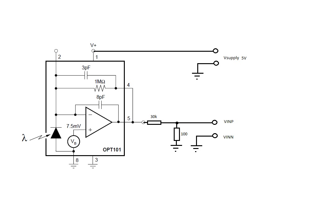
I´m recording EEG-Signals with my ADS1299EEG-FE. Since I need a time corresponding trigger event for my VEP, i took a channel input (let´s say channel 8) and connected it to the trigger generator. this trigger generator is actually a OPT101 from TI connected to the VEP-Screen. I used a voltage divider to reduce the voltage to millivolt which should be okay for the ADC. Finally I connected the Output of the diode to the positive Input for channel 8 (VINP) and the ground to the negative Input (VINN)

The problem now is the following:

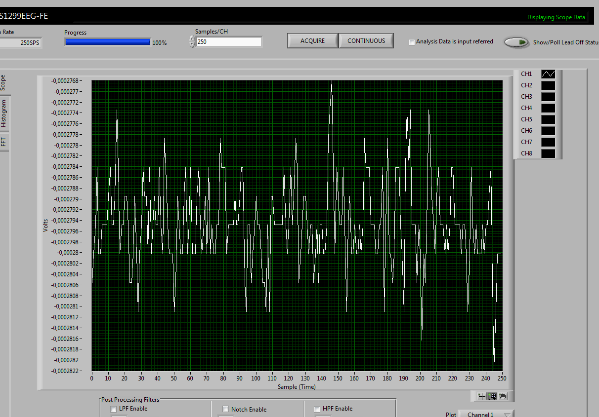
When I chose "normal electrode" for the diode (channel 8) in the corresponding register, I get just a noisy signal. when I chose "test signal" for the channel 8, I get a noisy signal (not only in channel 8). But when I chose "test signal" for all channels in the register, I get my signal and the diode does its job. But then there is no EEG recording in the other channels. For my recordings I use a reference electrode in one of the channels.

Please help me to get my system running.

Regards,

Markus

  • Hey Markus,

    Would you mind uploading a schematic?

    Brian
  • Hello Brian,


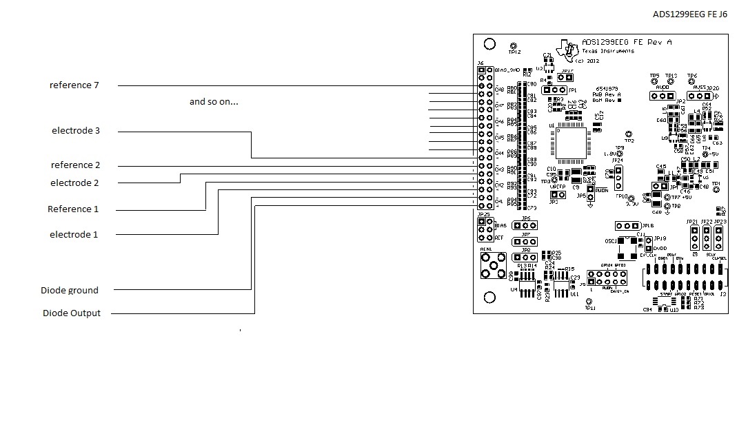
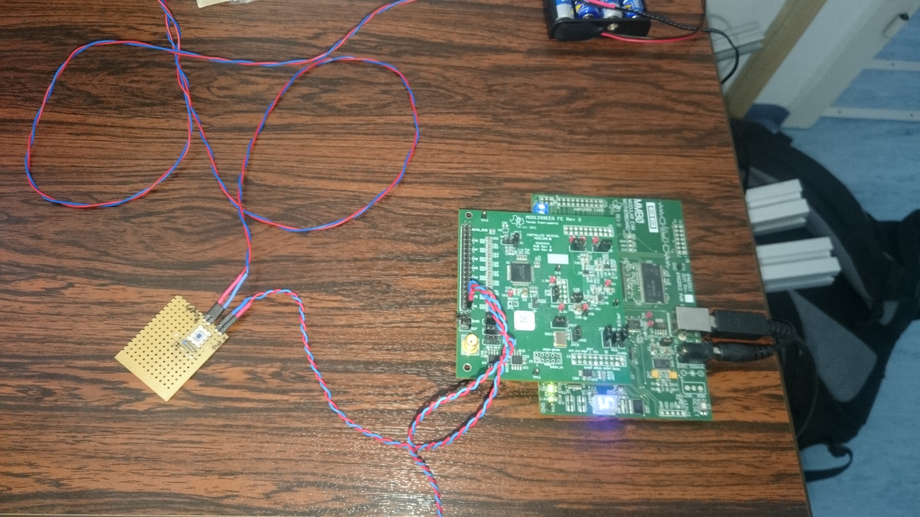
    unfortunately I´m not the greatest schematic artist, but I hope you can understand my setup with the help of these pictures.

    Regards,

    Markus

  • Hey Markus,

    I'm not quite sure what is causing the problem. How are the inputs being biased so they are within the measurement range of the ADS1299? Would you mind sending me the entire device register map for the various scenarios?

    Side note, connecting IN8N to the board ground might produce unexpected results since a voltage of AVSS is outside the device's conversion range as per Equation 2 in the ADS1299 datasheet. Would it be possible for you to instead connect the anode of the photodiode to the ADS1299's analog mid-supply voltage? From what I understand about the OPT101, the output will only experience a DC shift by that amount. The output is only Vb + Id*1MOhm; Id is a function of photon density so only Vb will change relative to ground. You may keep the OPT101's supply voltages at their current levels.

    Regards,
    Brian Pisani
  • Hello Brian,

    thank you for your Answer! I will send you the demanded pictures tomorrow when I´m back in the lab. Don´t get me wrong: the ground in the pictures above isn´t the board's ground. It´s the ground from the diode and its (extra) supply. By the way, the error also occurs when there is no other channel connected to electrodes. Is there a possibility to have the negative inputs separated from each other?

    Regards,

    Markus

  • Hey Markus,

    Your register settings look fine. The different grounds can be separated from one another. The grounds of the ADS1299 EVM board and the breadboard with the OPT101 on it should be tied together and the anode of the photodiode should be tied to an actively driven analog mid-supply voltage. It must be actively driven since I_c can change. One possible source could be the integrated bias amplifier on the ADS1299. It may be configured as a buffered mid-supply voltage, but you must ensure that the diode will never draw more than the rated short-circuit current for the bias amplifier, which is specified in the datasheet as 1.1 mA.

    Regards,
    Brian Pisani
  • Hello Brian,

    I linked the ADS1299EEG-FE's ground to the ground from the OPT101 and took the supply from the 5V-testpoint as diode supply. With these changes it worked. Thank you for your help!

    Regards,
    Markus