


Dear commmunity,
I am taking my first steps with the LMP90100 ADC and am very thankful for this community, I found a lot of solutions for the basic setup.
Nevertheless, I am stuck right now. I try to setup and programm the quick start from the datasheet.
10.1.1 Quick Start
This section shows step-by-step instructions to configure the LMP90xxx to perform a simple DC reading from
CH0.
1. Apply VA = VIO = VREFP1 = 5V, and ground VREFN1
2. Apply VINP = ¾VREF and VINN = ¼VREF for CH0. Thus, set CH0 = VIN = VINP - VINN = ½VREF
(CH0_INPUTCN register)
3. Set gain = 1 (CH0_CONFIG: GAIN_SEL = 0x0)
4. Exclude the buffer from the signal path (CH0_CONFIG: BUF_EN = 1)
5. Set the background to BgcalMode2 (BGCALCN = 0x2)
6. Select VREF1 (CH0_INPUTCN: VREF_SEL = 0)
7. To use the internal CLK, set CLK_EXT_DET = 1 and CLK_SEL = 0.
8. Follow the register read/write protocol (Figure 60) to capture ADC_DOUT from CH0.
As a Mikrocontroller I use an atmega2560(Arduino), that I programm with AtmelStudio.
What I figured from the upper description and the datasheet is that I wrote the registers as follows:
Initialisation:
0x10
0x02
0x00
0x01
0x01
0x71
0x10
0x01
0x00
0x02
Stream Configuration:
0x10
0x00
0x03
0x82
read SPI:
0x90
0x01
0xEA
0x00
0x00
0x00
MOSI:

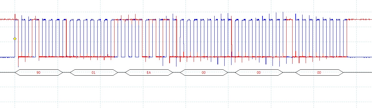
MISO:

The MISO Value is glued to 02, it does not change at all if the resistor to measure changes.
I used the following code:
#define F_CPU 16000000UL
#include <stdlib.h>
#include <avr/io.h>
#include <avr/interrupt.h>
#include <avr/pgmspace.h>
#include <util/delay.h>
#include "LMP90100/TI_LMP90100_register_settings.h"
#include "UART/uart.h"
#define UART_BAUD_RATE 9600
#define MOSI PB2 // Master Out, Slave In
#define MISO PB3 // Master in, Slave out (only used during ISP)
#define SCK PB1
#define SS PB0
#define SPI_DDR DDRB
#define SPI_PORT PORTB
void spi_init(void)
{
// all output beside MISO
SPI_DDR |= (1<<MOSI) | (1<<SCK) | (1<< SS);
SPI_DDR &= ~(1<<MISO);
// pullup for MISO
SPI_PORT |= (1<<MISO); // pullup prevents floating
// MSB is sent first
SPCR = (1<<SPE)|(1<<MSTR) | (1<<SPR0) | (1<<SPR1);// Enable SPI, set to Master
}
char ChanInit(void)
{
SPI_PORT &= ~(1<<SS); //chip select
uint8_t buffer0;
//uart_puts("0 ");
//send Instruction Byte 1
//while(!(SPSR & (1<<SPIF)));
// Byte 1: Instruction Byte 1
SPDR = 0x10;
//uart_puts(" Chan Init 1 ");
//Byte 2: Upper Adress Byste
while(!(SPSR & (1<<SPIF)));
SPDR = 0x02 ;
//uart_puts("2 ");
//Byte 3: Instruction Byte 2
while(!(SPSR & (1<<SPIF)));
SPDR = 0x00;
//uart_puts("Chan Init 3 ");
//Byte 4: Data Bytes (dummies if receiving)
while(!(SPSR & (1<<SPIF)));
SPDR = 0x01;
//uart_puts(" Chan Init 4 ");
while(!(SPSR & (1<<SPIF)));
SPDR = 0x01;
//uart_puts(" Chan Init 5 ");
while(!(SPSR & (1<<SPIF)));
SPDR = 0x71;
//uart_puts(" Chan Init 6 ");
while(!(SPSR & (1<<SPIF)));
SPDR = 0x10;
//uart_puts(" Chan Init 7 ");
while(!(SPSR & (1<<SPIF)));
SPDR = 0x01;
//uart_puts(" Chan Init 8 ");
while(!(SPSR & (1<<SPIF)));
SPDR = 0x00;
//uart_puts(" Chan Init 9 ");
while(!(SPSR & (1<<SPIF)));
SPDR = 0x02;
//uart_puts(" Chan Init 10 ");
//Byte 5: Data Bytes (dummies if receiving)
while(!(SPSR & (1<<SPIF)));
buffer0 = SPDR; // read 1. response byte
//SPDR = 0x00;
//uart_puts("Chan Init 11");
//while(!(SPSR & (1<<SPIF)));
//buffer = SPDR; // read 2. response Byte
SPI_PORT |= (1<<SS);
//uart_puts("Chan Init 12\n");
return buffer0;
}
char StreamConf(void)
{
SPI_PORT &= ~(1<<SS); //chip select
uint8_t buffer1;
//uart_puts("0 ");
//send Instruction Byte 1
//while(!(SPSR & (1<<SPIF)));
// Byte 1: Instruction Byte 1
SPDR = 0x10;
//uart_puts("StreamConf 1 ");
//Byte 2: Upper Adress Byste
while(!(SPSR & (1<<SPIF)));
SPDR = 0x00;
//uart_puts("StreamConf 2 ");
//Byte 3: Instruction Byte 2
while(!(SPSR & (1<<SPIF)));
SPDR = 0x03;
//uart_puts("StreamConf 3 ");
//Byte 4: Data Bytes (dummies if receiving)
while(!(SPSR & (1<<SPIF)));
SPDR = 0x82;
//uart_puts("StreamConf 4 ");
//Byte 5: Data Bytes (dummies if receiving)
while(!(SPSR & (1<<SPIF)));
buffer1 = SPDR; // read 1. response byte
//SPDR = 0x00;
//uart_puts("StreamConf 5 ");
//while(!(SPSR & (1<<SPIF)));
//buffer = SPDR; // read 2. response Byte
SPI_PORT |= (1<<SS);
//uart_puts("StreamConf 6\n");
return buffer1;
}
char SPIreadExample(void)
{
SPI_PORT &= ~(1<<SS); //chip select
uint8_t buffer2;
//uart_puts("0 ");
//send Instruction Byte 1
//while(!(SPSR & (1<<SPIF)));
// Byte 1: Instruction Byte 1
SPDR = 0x90;
//uart_puts("1 ");
//Byte 2: Upper Adress Byste
while(!(SPSR & (1<<SPIF)));
SPDR = 0x01 ;
//uart_puts("2 ");
//Byte 3: Instruction Byte 2
while(!(SPSR & (1<<SPIF)));
SPDR = 0xEA;
//uart_puts("3 ");
//Byte 4: Data Bytes (dummies if receiving)
while(!(SPSR & (1<<SPIF)));
SPDR = 0x00;
//uart_puts("4 ");
while(!(SPSR & (1<<SPIF)));
SPDR = 0x00;
//Byte 5: Data Bytes (dummies if receiving)
while(!(SPSR & (1<<SPIF)));
buffer2 = SPDR; // read 1. response byte
uart_putc(buffer2);
SPDR = 0x00;
//uart_puts("5 ");
while(!(SPSR & (1<<SPIF)));
buffer2 = SPDR; // read 2. response Byte
uart_putc(buffer2);
SPI_PORT |= (1<<SS);
//uart_puts("5\n");
return buffer2;
}
int main (void)
{
// init uart for debugging
uart_init( UART_BAUD_SELECT(UART_BAUD_RATE,F_CPU) );
_delay_ms(5000);
// global interrupt activation
sei();
spi_init();
ChanInit();
StreamConf();
while(1)
{
_delay_ms(1000);
SPIreadExample();
}
return 0;
}
My problem is, that I do not get any significant MISO signal, it just does not read the resistor I placed on CH 0, differential.
My first question is, did I do any obvious mistake? Can anyone help me with that? Is there any full example to read DC on CH0.
The second question ist, is it possible to just read a resistor with one end attached to GND?
Thank you all very much in advance for your help.
