This thread has been locked.

If you have a related question, please click the "Ask a related question" button in the top right corner. The newly created question will be automatically linked to this question.

DAC3482EVM with TSW1400EVM

Other Parts Discussed in Thread: DAC3482, CDCE62005

Hello,

I have purchased the TSW1400 and DAC3482EVM evaluation kits and started testing using the TI provided tools and firmware.

I am not feeding the external clock for DAC3482EVM instead using 19.2MHz on-board clock.

The HSDC pro tool generates a simple sine wave of 10MHz frequency at 250MSPS rate.

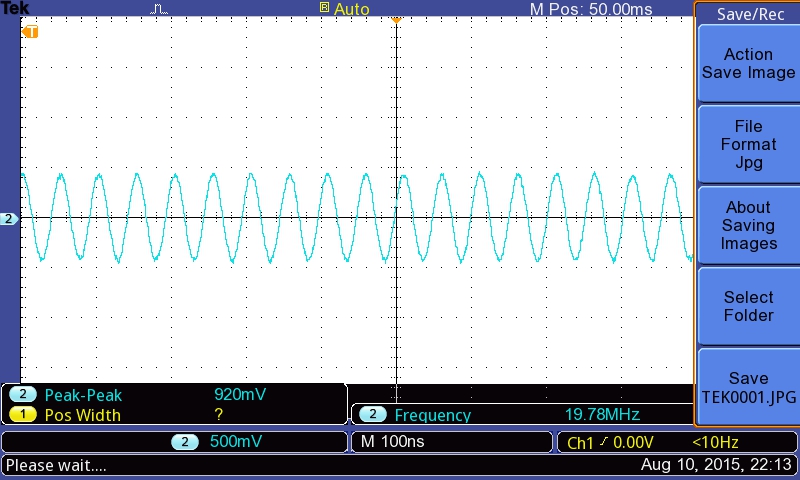
But in the DAC output  I am observing sine wave of around 20MHz with 920mVpp. [The gain is set to 10(20mA full scale current).]

Can you check the attached DAC-EVM register settings and let me know which settings got  missed.

With Regards,

Hariprasad Bhat

   x00	   xF188
   x01	   x0020
   x02	   xF850
   x03	   xA001
   x04	   xFFFF
   x05	   x0760
   x06	   x2F00
   x07	   xFFFF
   x08	   x0000
   x09	   x8000
   x0A	   x0000
   x0B	   x0000
   x0C	   x05A6
   x0D	   x05A6
   x0E	   x05A6
   x0F	   x05A6
   x10	   x3000
   x11	   x0000
   x12	   x0000
   x13	   x0000
   x14	   x0000
   x15	   x07D0
   x16	   x0000
   x17	   x07D0
   x18	   x205F
   x19	   x10F4
   x1A	   x4820
   x1B	   x0800
   x1C	   x0000
   x1D	   x0000
   x1E	   x1188
   x1F	   x8882
   x20	   x2400
   x22	   x1B1B
   x23	   x001F
   x24	   x1000
   x25	   x7A7A
   x26	   xB6B6
   x27	   xEAEA
   x28	   x4545
   x29	   x1A1A
   x2A	   x1616
   x2B	   xAAAA
   x2C	   xC6C6
   x2D	   x0000
   x2E	   x0000
   x2F	   x0000
   x30	   x61A8
   x7F	   x0004
CDCE62005 Registers
Freq:19.200000MHz
Address	Data
00		80400000
01		811C0321
02		81400302
03		81040303
04		00040304
05		38101A85
06		04BF1F76
07		151877F7
08		20001C08

  • Hi Hariprasad,

    I have created the new thread for this post. So that the assigned expert can reply to this.

    Regards,
    Neeraj
  • Hello,

    Most likely the frequency tone error is due to the tone generated by HSDC PRO is sampled at 250MSPS but the actual DAC operating data rate is at something else. Please advise that if you had configured the DAC3482EVM with 491.52MSPS input data rate, 2x interpolation, and 983.04MSPS of DAC rate after interpolation. This will cause the frequency error.

    You may want to change the data rate setting on your HSDC PRO and regenerate the tone at 491.52MSPS.

    -Kang
  • Hello,

    Any updates regarding my above query?

    With Regards,
    Hariprasad Bhat
  • Hello Kang,

    Thank you for the suggestion. I will try this and update you.
    Regards,
    Hariprasad Bhat
  • Hello Kang,

    I continued my testing by setting 491.52MSPS at HSDC tool and configuring DAC in x2 mode.

    My requirement is to have 20mA full scale current output with 0.5Vp-p  Amplitude. 

    Following are my observations.

    1. The I and Q channel outputs are in phase [Not differed by 90 degree phase].
    2. As I increase the signal frequency the Amplitude of the waveform gets reduced. In ordered to maintain the amplitude I increased QMC gain value.

    Also I have attached the snapshots of HSDC tool settings, DAC3482-EVM software tool settings and observed waveform.

    Please suggest me for any missed configurations.

    Also, suggest me what will be the maximum frequency of the signal I can feed from TSW1400EVM so that I can get the Analog equivalent from DAC3482 without any distortion or harmonics.

    Regards,

    Hariprasad Bhat

    DAC3482_testing_snapshots.zip

  • Hariprasad,

    1. The I and Q channel outputs are in phase [Not differed by 90 degree phase].

    you will need to generate the baseband I/Q signal in complex domain, not real domain. On the HSDC PRO GUI, lower left hand corner, please select complex tone instead of real tone

    2. As I increase the signal frequency the Amplitude of the waveform gets reduced. In ordered to maintain the amplitude I increased QMC gain value.

    This is fine. The DAC itself as have inverse sinc filter to compensate higher frequency roll-off due to the sampling nature of the DAC (this applies to all DACs with finite sample response). You can go to the digital tab to enable inverse sinx/x roll-off filter.

    For more details of this, please refer to the DAC3482 datasheet.

    -Kang

  • Hello Kang,

    Thank you for the explanation. Indeed useful.

    The setup is working fine with 491.52MSPS datarate from HSDC tool.

    I want to go with around 1GSPS[x1interpolation ]. How can I configure the DAC as well as CDCE62005 which generates DAC_CLK, OSTR and FPGA clocks.

    [Currently I am not enabling PLL under PLL Settings tab of DAC3482evm tool.] OR

    Is it possible to share the configuration files with the following settings so that I can load the same to DAC-EVM tool.

    Below are the 2 major concerns.

    DATA sampling rate : 1GSPS

    CDCE62005 with secondary REF clock with 19.2MHZ on-board clock.

    With Regards,

    Hariprasad Bhat

  • Hariprasad,

    The DAC3482 does not support 1Gsps of input data rate. The max is 625MSPS. Please refer to the device datasheet and EVM user's guide for the supported modes and specifications.

    -Kang

  • Hi Kang,

    Yes. it supports 625MSPS max.

    Basically I want to understand the PLL settings wrt the change in data rate.

    So, I have the below questions.

    How can I configure the DAC as well as CDCE62005 which generates DAC_CLK, OSTR and FPGA clocks with respect to different data rates[MSPS].

    [Currently I am not enabling PLL under PLL Settings tab of DAC3482evm tool.] 

    For CDCE62005 , secondary REF clock  is 19.2MHZ on-board clock [no external clock is provided from J9].

    Can you please come back on above queries?

    With Regards,

    Hariprasad Bhat

  • Hariprasad,

    For the DAC3482 on-chip PLL configuration, please refer to the following app note:
    www.ti.com/.../slaa520.pdf

    For the CDCE62005, there are some utilities on the web to help you configure the right VCO and divider settings. I think the EVM software would help. You may post questions on the clocking forum regarding the CDCE62005.
    www.ti.com/.../scac105

    -Kang
  • Hello,

    I am trying to test with custom patterns. I am generating the .csv file with coefficients. This csv file is  being loaded to HSDC tool. But in the DAC output I am getting different patterns. Looks like I am getting kind of mirrored pattern. Attached the HSDC tool waveform snapshot as well as Oscilloscope capture from DAC output. Also, attached the .csv coefficient file.

    Can you please guide me to get the correct output?

    Regards,

    Hariprasad Bhat

    https://e2e.ti.com/cfs-file/__key/communityserver-discussions-components-files/73/Custom_5F00_pattern.7z

  • Hariprasad,
    The default DAC3482EVM has transformer coupled output, which has a bandpass response. For step response which has a flat top over some period of time, the high pass portion of the response will filter it out. Hence you are observing a round top for the measured response.
    If you need to have DC coupled option, you will need to terminate the DAC with resistors. See below app note for detail:
    www.ti.com/.../slua647a.pdf-Kang
  • Hello Kang,
    Thank you for this information.
    But, if you compare the HSDC wave form and captured waveform[180 degree rotated], you will find HSDC waveform in the captured screenshot through flattened portion is groomed. Can you tell me why the wave forms from HSDC is appearing in the reverse way at DAC output?
    Regards,
    Hariprasad Bhat
  • Also, If I want to terminate with resistors, do I need to unmount any of components in the DAC3482EVM board?
  • Hariprasad,

    You may need to look into the DAC option on the HSDC PRO GUI whether it is set to 2's complement or offset binary. This will have to match the DAC setting.

    The resistive termination requires changes/soldering to the DAC3482 EVM board.

    -Kang