This thread has been locked.

If you have a related question, please click the "Ask a related question" button in the top right corner. The newly created question will be automatically linked to this question.

Why does the ADS1263 Back Drive 5V to the analog inputs at power on?

Other Parts Discussed in Thread: ADS1263

We designed in the ADS1263 as per TI's recommendation as a current sense ADC.  The differential inputs are across a current sense resistor on a 1.8V rail.  When the system power is turned on the ADS1263 back drives +5V out the inputs.  The 1.8V rail is off and the ADS1263 forces it's potential to 5V, jeopardizing the logic integrity on that rail.

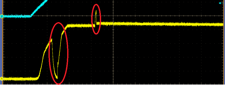
The picture below is the behavior we see at power up on one of the worst units.  Other units show only the first glitch and don't come all the way up to 5V.

Can anyone explain this?

  • Hi Martin,

    Welcome to the TI E2E forums!

    Would you be able to supply a schematic of your circuit?
    You can email it directly to me at this email address: pa_deltasigma_apps@ti.com.

    It appears like your input is settling to a voltage that is roughly a diode drop below the AVDD supply. The ADS1263 has diode connections between the inputs and AVDD, and it is likely that one or more of  the inputs are over-ranged and turning on these diodes. Have you probed the other inputs (with respect to the ADC ground) to make sure the input range of the ADC is not being violated?

    Best Regards,
    Chris

  • When the AVDD (5V) and DVDD(3.3V) power rails turn on, the ADS1263 itself is back driving voltage to its input pins. The inputs are connected to de-energized circuits which are expected to stay at zero volts with respect to ADC ground until some later time. The input range of the digital inputs is specified to be 300mV below ground to 300mV above the DVDD rail, so the expected 0V is within that range. I have seen this on other inputs and on other platforms. The problem is sporadic and some platforms exhibit the problem worse than others. I'll post more scope captures as I get them. Regarding the schematic, if you have an NDA with Intel for this project I can share that with you in some more secure forum.
  • Here are two scope captures.  Channel 1 is connected to pin 1 AIN8 of the ADS1263.  Channel 2 is connected to the 5V power supply that provides AVDD.  The first picture is with AVDD connected to the 5V supply.  The second picture is the exact same setup but the AVDD pin is disconnected from the 5V supply.

  • Hi Martin,

    I'll do my best to help with the information given. I've asked our FAEs to reach out to you. I believe they would be the ones to who handle NDA's.

    Under recommended operating conditions the analog inputs are high impedance and would not drive the input signals. You've shown that a current path exists between the analog input and analog supply. The only way for these inputs to become low-impedance is when the input ESD diodes turn-on. This happens when the input voltage is outside one of the supply voltages by more than a diode drop.

    From your oscilloscope screenshot, it appears like the input voltage is tracking the analog supply voltage...

    Try measuring the voltage across an input resistor; I'm certain you'll find the current direction to be going into the ADC input!

    Next, you'll need to follow the current path and determine how the circuit is being completed. Perhaps the de-energized supply connected to the ADC input is being back driven through another direction - at the very least you know that there is another conduction path between the analog supply and analog input outside of the ADC itself. Likely something in your system is not properly referenced to ADC ground.

    Certainly, if the ADC's inputs were powered before the ADC's analog supply, the input signal could back drive the analog supply. However, the ESD diode polarity would not allow for the opposite condition to occur! (We test every device for continuity; therefore, we'd know if an ESD diode was backwards!)

    Best Regards,
    Chris

  • Chris,

    The ESD diode theory doesn't offer a plausible explanation.  If something were driving the input when the AVDD rail to the device is disconnected we should see the input voltage rise to the diode drop.  We don't see that .  We see that when AVDD is disconnected from the ADS1263 the input is zero.

    To reiterate, the two scope captures I posted are exactly the same setup except the AVDD pin of the ADS1263 is open in the case where the input remains at zero volts.

    Also, there is no other logic on any of the inputs that is powered by the 5V rail.  In fact, everything connected to the inputs is de-energized.  The only path from 5V to the input is through the ADS1263, and when 5V is removed from the AVDD pin, the inputs remain at zero volts.

    Again, this behavior is not consistent across all ADC1263 devices.  Some exhibit only a small glitch and others don't have the problem at all.  We had to pick the few units from roughly 20 to get consistent bad behavior on the bench.  I know this is a new ADC offering and perhaps there has been some test hole or manufacturing anomaly.  I look forward to demonstrating this problem to the FAE.

    Sincerely,
    Martin Goodman
    Intel Corporation

  • Hi Martin,

    I was mistaken about the current path, the input voltage would need to be a diode drop ABOVE the AVDD supply rail in order for current to flow. As you've showed in your scope shot the input voltage it actually a diode drop BELOW the AVDD supply. Nevertheless, the ESD diode only allows current to flow in one direction (from the input to the supply; not the other way around, unless the device has been damaged).

    Here are some additional questions I have...

    • Might you have something else on your board connected to AVDD? (if there is an external input protection diode somewhere that was connected backwards, it would explain some of the behavior.)

    • How are AVDD and the 1.8V rail your monitoring generated?

    • Where do the grounds of each supply connect?

    • Are there any inductors on these supplies?

    • Are there any signals applied to the ADS1263 before the power supplies (AVDD and DVDD) are applied?

    • One thing that is odd is that the input signal is not perfectly tracking AVDD. There are two spikes that seem to indicate that something else in the circuit is turning on. Is this current going into the load on the supply your monitoring? It would be good to measure the differential voltage across the shunt resistor to understand where the current is going. You should also try removing the shunt resistor to see if this breaks the conduction path.

    • Have you tired measuring the resistance on your PCB between AVDD and the 1.8V supply, with no power applied? Maybe you don't have any schematic connections between the AVDD and 1.8V supplies, but there could be a manufacturing defect creating a type of short.

    • Can you measure the resistance and diode drop between AIN8 and AVDD with a DMM to see if the ESD diode is damaged?

    • What happens to AIN8 when you energize your 1.8V supply?

    Best Regards,
    Chris

  • Working off line we determined that the root cause of the issue is the power sequencing of the two power rails, DVDD and AVDD. If AVDD comes up before DVDD the input mux is in an indeterminate state.  This can allow AVDD to momentarily back drive some of the analog inputs. The solution for my design is to gate AVDD with DVDD.