This thread has been locked.

If you have a related question, please click the "Ask a related question" button in the top right corner. The newly created question will be automatically linked to this question.

ADS1234 Additive value

Other Parts Discussed in Thread: ADS1234

hi every one

i designed a very sample circuit without any input cap , inductor and ... for AINNX and AINPX pins

i tied all AINPx AINNx pins to AGND and riding the digital data from ads1234

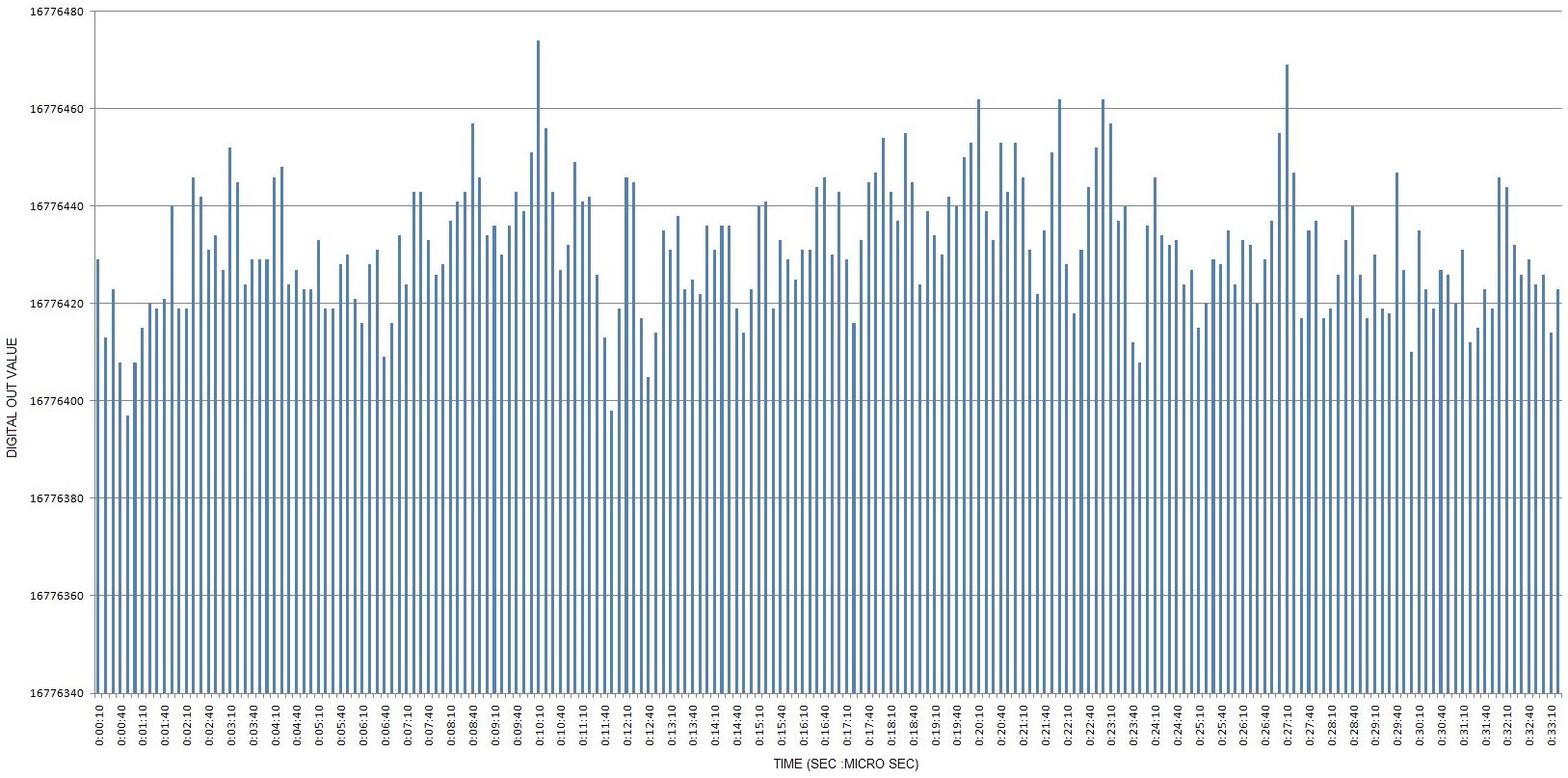
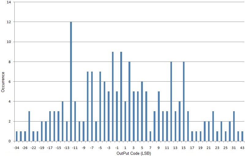
but without any changing of AINN & AINP ,digital data is Additive  !!!

i get 100 sample in 20 min and you can see the results of test in this  diagram

AVDD=3.3v

DVDD=3.3v

VREFP=3.3V

VREFN=AGND

PGA=128

10 SPS

for power supply i used ncp700 that  has output noise less than 15µv rms

best regards 

alireza roozitalab

  • Hi Alireza,

    I suspect what you are seeing is due to your exceeding the common-mode input range specification.  Using the gains of 64 or 128 the input must be in the range of (AGND + 1.5V) < Vin < (AVDD - 1.5V).  Shorting the inputs to AGND violates this specification.  I would suggest creating a voltage divider using two equal value resistors between AVDD and AGND.  At the midway point of the voltage divider (AVDD/2) short your inputs at that point to maintain the appropriate common-mode.

    Best regards,

    Bob B

  • hi Bob,

    i use two 240 Ω (near to a loadcell resistor) resistor as divider and check the voltages by keysight multi-meter

    AVDD to AGND = 3.30746 V

    AINN1 & AINP1 to AGND =1.65458V

    AINN(2,3,4) & AINP(2,3,4)  are tied to AGND  yet

    and the digital value for AINN1 & AINP1 was  0x001620  at the beginning and after bout 10 min the digital value was 0x001AA0

    Best regards,

    Alireza R

  • Hi Alireza,

    Can you send me your schematic?  As it appears that you can change your system quickly, are you using a prototyping board such as a white breadboard?  It is not impossible, but it is very difficult to get high performance from these types of prototyping systems due to noise pickup, oscillation and poor grounding.

    In the original posting you mentioned no caps, etc. on the analog inputs, but there should be caps at some other pins.  You should have caps on your supply input pins for bypassing, and you must have a cap across pins 9 and 10.  It may also be beneficial to have a differential cap across the analog input pins even with the short (especially if there are loops of wires connecting to the inputs).  All caps should placed as close as possible to the input pins.  All bypass caps should have a low impedance ground connection. 

    There appears to be something in your system that is drifting more than the self-heating of the ADC.  I would double check all connections, especially any connections from the supply and ground.  And make sure you have a 0.1uF cap across pins 9 and 10 as this cap not only filters noise but also helps to improve temperature drift.

    Best regards,

    Bob B

  • Hi Bob,

    i checked datasheet before and i have necessary capacitors in my design and  top an bottom GND polygon in my pcb

    even i have 100pf common mode caps and 100nf differential cap on each AINNX & AINNPX that have been dis Assembled

    schematic of my testing  by now:

     i use sn74hc356  as tri-state buffer for spi interface

    Best regards

    Alireza r

  • Hi Alireza,

    Have you issued a self calibration?  It would be good to make sure there is no offset to the device from your external connection and issuing the self calibration would remove any ADC offset from the calculation.  Also, it would be good to see raw data results from at least 100 continuous data samples instead of the periodic samples you have provided.  Can you tell me more about how you are collecting the data?  Are you powering up and down the ADC?

    Best regards,

    Bob B

  • Hi Bob

    first i had improved power supply and my soldering 

    and put back two 100pf cap as deferential cap and  one 100nf cap as common mode cap

    i removed the tri_state buffer and connected ads1234 directly to micro via spi interface

    and adding  self calibration on the beginning of my micro-controller source by sending 26 pulses on SCLK  (i had not self calibration on my source before)

    i do not powering up and down the adc , in my schematic i use 1kΩ resistor and 100nf cap on the PDOWN pin

    in micro-controller src  after self calibration if drdy interrupt has been occur  then i read 24 bit data from spi and sending data immediate via usart to pc and  storing the data

    now i have  three new diagram with these Changes as you see in the below

    this diagram is 100 samples on the start up of system:  my started data  was around  0xFFFDFC and after 13 min my data was around 0xFFFD02

    and after 10 hour i checked  it again and noise of the system too by 200 samples in 30 seconds 

  • Hi Alireza,

    Thanks for the information.  Looking at the overall noise, it appears that your noise-free resolution is good, but the distribution is not evenly distributed about a mean.  From the 30 second data plot there appears to be a very low frequency periodic noise source within the plot, and that might be what is causing the uneven distribution. 

    Another thing I noticed is that on startup, the values are not what I would expect for a shorted input case after calibration.  They should be much closer to 0.  As this is binary two's complement, the values your are showing are actually negative code values being returned.  The largest values are closer to 0 (0xFFFFFF is one code less than 0).

    There are a couple of possible reasons for seeing an offset.  One is a very noisy reference where there are issues with getting a stable offset calibration.  Another possibility is there is a true external offset that is being created.  Sometimes there are thermocouples that are created within the path due to wiring and connections and a difference voltage is then created at the analog inputs. Fans blowing or air currents traveling along the input path may create a variation in the measurement.  A method to check this is to short the input pins at the ADS1234.  I've used an actual solder short in the past to check this, but you will still need to bias the input to the correct common mode.

    It is possible that the ADS1234 is drifting.  Issuing a periodic offset calibration should take care of this type of drift.  Verify that you are truly using a gain of 128, and not some other gain.  Issue the offset calibration after any change in gain.

    There are a couple of other things you may want to look at to see if they are issues.  One is trying to issue the self calibration more often ( instead of just after power up) to eliminate any affects of initial self-heating.  Another is attempting to discover both the low frequency noise (if indeed it is truly present) and why there is initial offset.

    Best regards,

    Bob B