Other Parts Discussed in Thread: ADS1256
hi,
We are using the ADS1256 at 30kS/s rate, PGA=1.
When applying a 100mV 500Hz sine wave to the input, we found strange spikes on the converted digital output.

See line 13, 73, 98 in the data recording (.txt):
6fa55,
72e32,
76712,
767e3,
7a6e3,
833b4,
87d01,
8c9f9,
8c92c,
9172c,
9ac3f,
9f434,
93a78,
a3a16,
a7e16,
af547,
b281c,
b564f,
b56de,
b7fde,
bbdae,
bd358,
be3e0,
be344,
bef44,
bf153,
be9a1,
bdb5f,
bdbba,
bc6ba,
b8a94,
b6401,
b38b6,
b38b7,
b08b7,
a965f,
a5659,
a146f,
a1408,
9cf08,
93808,
8ea78,
89dd6,
89d1d,
8521d,
7c02e,
77b0d,
73c2f,
73c0a,
7030a,
6a2cd,
67efb,
66409,
66490,
65190,
6485a,
6512d,
664f0,
6649d,
6819d,
6cf60,
70207,
73dbc,
73d2a,
77d2a,
8094b,
8535d,
8a0e8,
8a084,
8ee84,
985be,
9ce01,
915b7,
a1584,
a5a84,
ad496,
b09b0,
b38cd,
b3814,
b6214,
ba333,
bb9d4,
bcacf,
bca7a,
bd67a,
bd95b,
bd10c,
bc47b,
bc414,
bb114,
b7668,
b4f56,
b23b6,
b23d3,
af3d3,
a814a,
a4193,
afe71,
9fe79,
9b779,
9207e,
8d18c,
88419,
88431,
83831,
7a4bb,
75f04,
71f90,
71fd9,
6e5d9,
68262,
65e1f,
642bc,
64206,
62f06,
6234c,
62b5e,
63ed3,
63eeb,
65aeb,
6a7d6,
6db25,
615db,
71571,
75571,
7e13c,
82b6d,
879fe,
87919,
8c919,
96105,
9ab6e,
9f314,
9f344,
a3844,
ab488,
aeb6a,
a1b8e,
b1bbe,
b45be,
b88a6,
ba036,
bb263,
bb2d2,
bbed2,
bc27f,
bba8d,
badba,
bad40,
b9b40,
b60eb,
b3bc2,
b10e5,
b10ab,
adfab,
a6e67,
a2e9e,
aea5f,
9ead4,
9a2d4,
909c5,
8bb49,
86e76,
86eca,
821ca,
78bdb,
745bb,
704f0,
70472,
6ca72,
6666f,
640c7,
62506,
625ac,
60fac,
6018c,
60980,
61a30,
61a5a,
6355a,
682ff,
6b4a9,
6ef61,
6ef10,
73010,
7ba64,
806c0,
85539,
85588,
8a488,
93f03,
98958,
9d2de,
9d2cb,
a18cb,
a95cb,
acd34,
a0032,
b0035,
b2c35,
b6fe6,
b88c7,
b9c9e,
b9ceb,
ba8eb,
bae1d,
ba6cf,
b9a55,
b9a93,
b8793,
b4ee4,
b28f8,
bfee3,
afed1,
acdd1,
a5bde,
a1b0b,
ad7d5,
9d70c,
9910c,
8f80f,
8a881,
85a96,
85a2f,
80e2f,
774f6,
72dc7,
7ecf1,
6ec35,
6b035,
64c17,
623e9,
6062e,
60672,
5f172,
5e269,
5e8a1,
5f9ec,
5f975,
61375,
66083,
69216,
6ccd0,
6cc27,
70d27,
79829,
7e36c,
732f3,
832b0,
882b0,
91dfe,
9699c,
9b3c4,
9b3d9,
e.g.
sample 12. 0x9f434,
sample 13. 0x93a78,
sample 14. 0xa3a16,
Simply setting the conversion rate to 15kS/s cause these spikes to disappear.
We tried different PGA values also at 30kS/s. Using PGA 2,4,8, 16 did not solve it, the spikes were still present.
It seems as it were a digital data latching issue in the conversation handling STM.
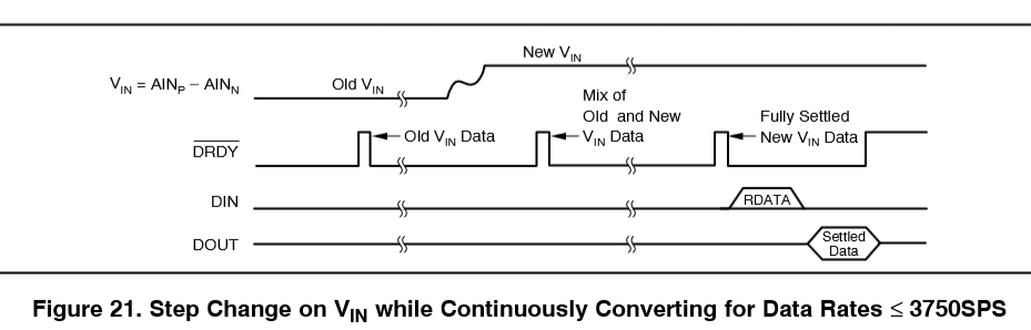
From Page 22 in the ADS1256 datasheet:
“If there is a step change on the input signal while continuously converting, performing a synchronization operation to start a new conversion is recommended. Otherwise, the next data will represent a combination of the previous and current input signal and should therefore be discarded.”
However this note on discarding interim results contradicts the very idea of the continuous measurement. Obviously the user is applying this mode when he is interested in the timely behavior of the input signal. Hence he is not in the position to “restart” the measurement if there is a change on the input signal.
More importantly the sine wave should not present any sort of “step change” for the ADC.
Question: how can avoid this unwanted behavior while using the highest possible conversion rate?
Thank you,
Andras