This thread has been locked.

If you have a related question, please click the "Ask a related question" button in the top right corner. The newly created question will be automatically linked to this question.

ADS1299 is working but readings are far from correct!

Other Parts Discussed in Thread: ADS1299

Hello!

I am working with the ADS1299 and currently I implemented the whole circuit in a protoboard.

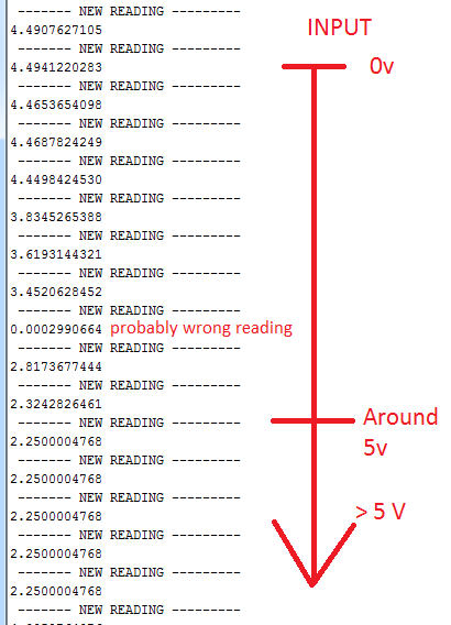
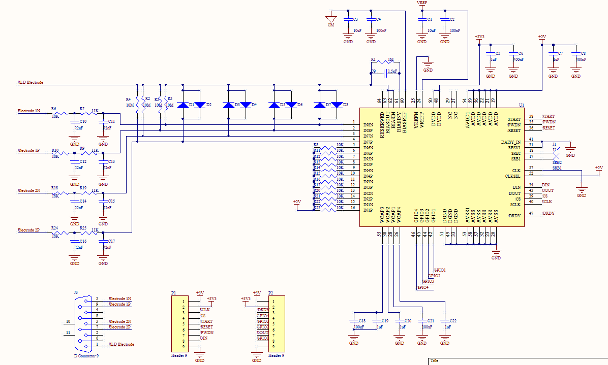
I am using unipolar configuration and used the following schematic (and also datasheet of course)

I am using ARDUINO MEGA 2560 in order to communicate with it. The whole thing seems to be working fine. I can read and write registers, I can actually read different values for different settings, etc...

Even though I can go from one input method to another (internal testing, temperature, input short, etc...), the values aren't fine.

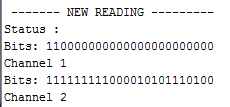
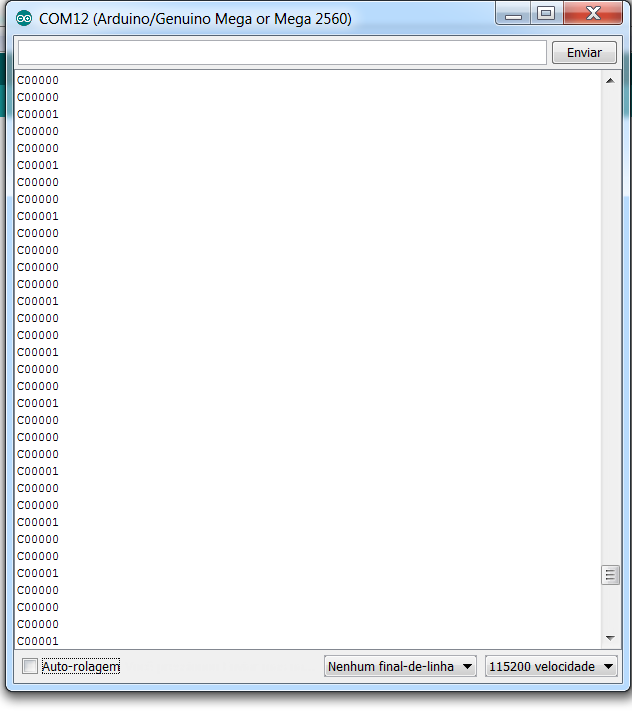
Another thing that I noticed is that my status register often gets one bit that it shouldn't (Should stay at C00000, but sometimes it becomes C00001).

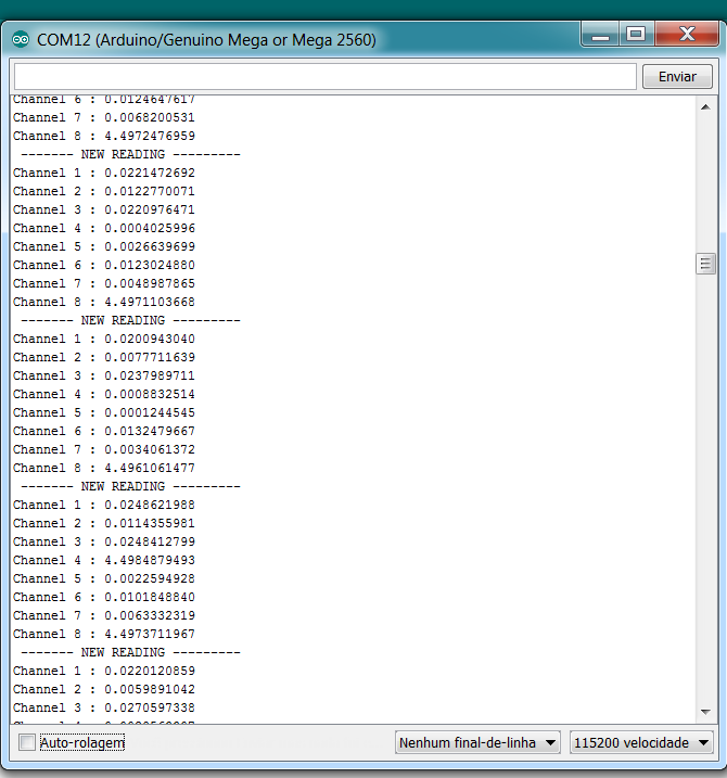
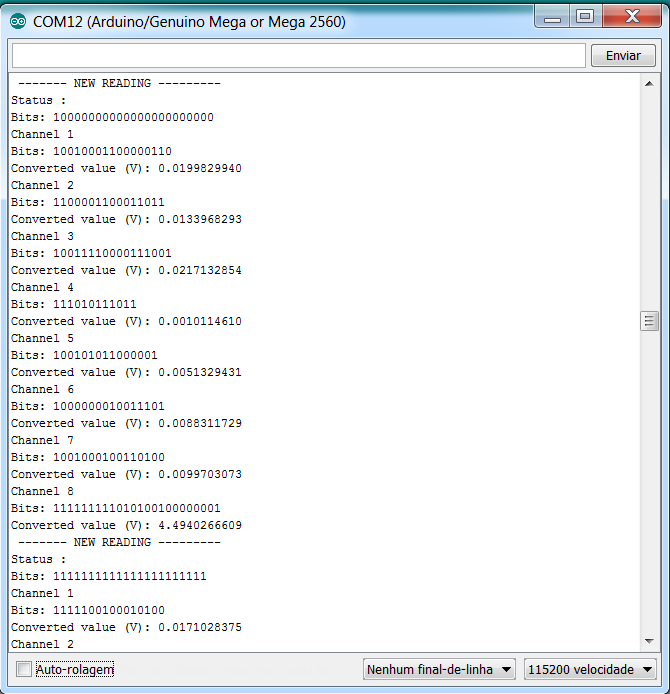
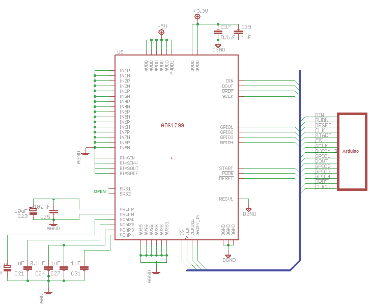
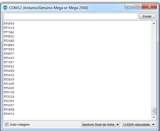
Here are some screenshots using arduino serial to get the values. I actually get STATUS + 8 channels data, that is working fine.

Each reading happens at each millisecond.

But on the screenshots only printed channel 1.
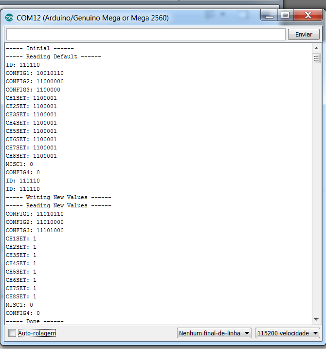
Status register:

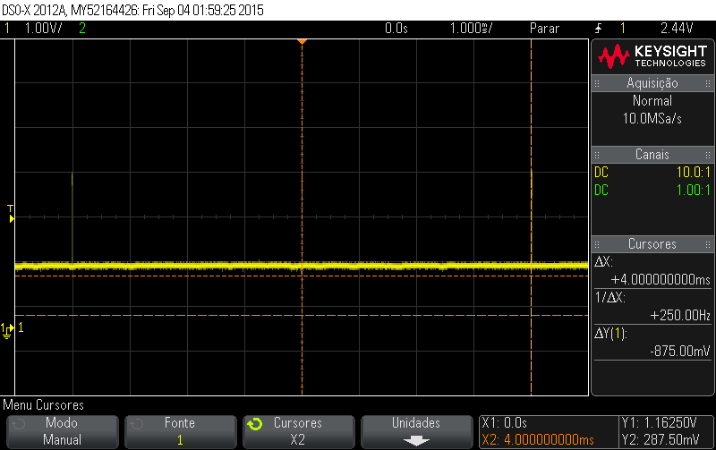
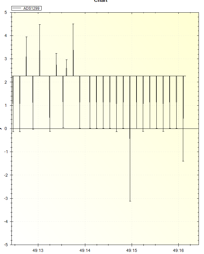
Temperature reading: this is how I suppose things are working fine. When in temperature reading mode,

the values are almost constant and aren't very high (unlike the other modes).
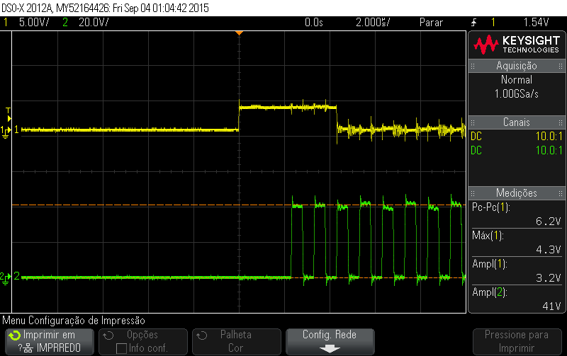
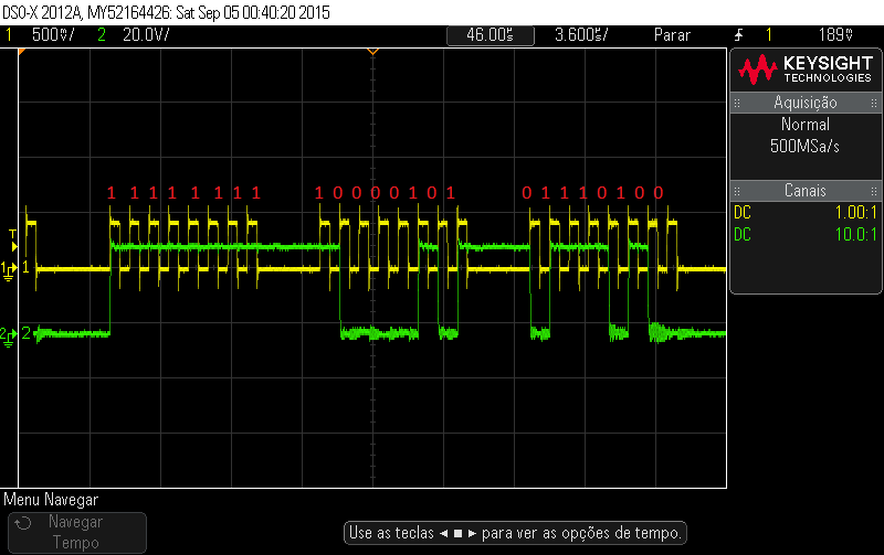
Test signal:

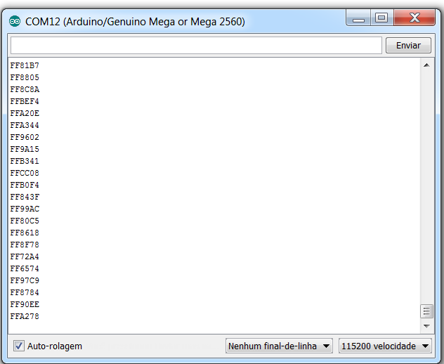
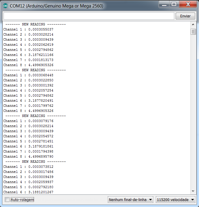
Normal input electrodes (with both CHN1P and CHN1N grounded):

Btw, Input short gives me roughly the same output.

So... I am really lost here. I've tried lots of different schematics, but I always get values that are waaay to high!

I've already checked thousands of times, and my internal reference is 4,5V, DVDD 3v and AVDD 5v.

Could it be power line noise (considering I am using no batteries at all?) or faulty VCAPs ?

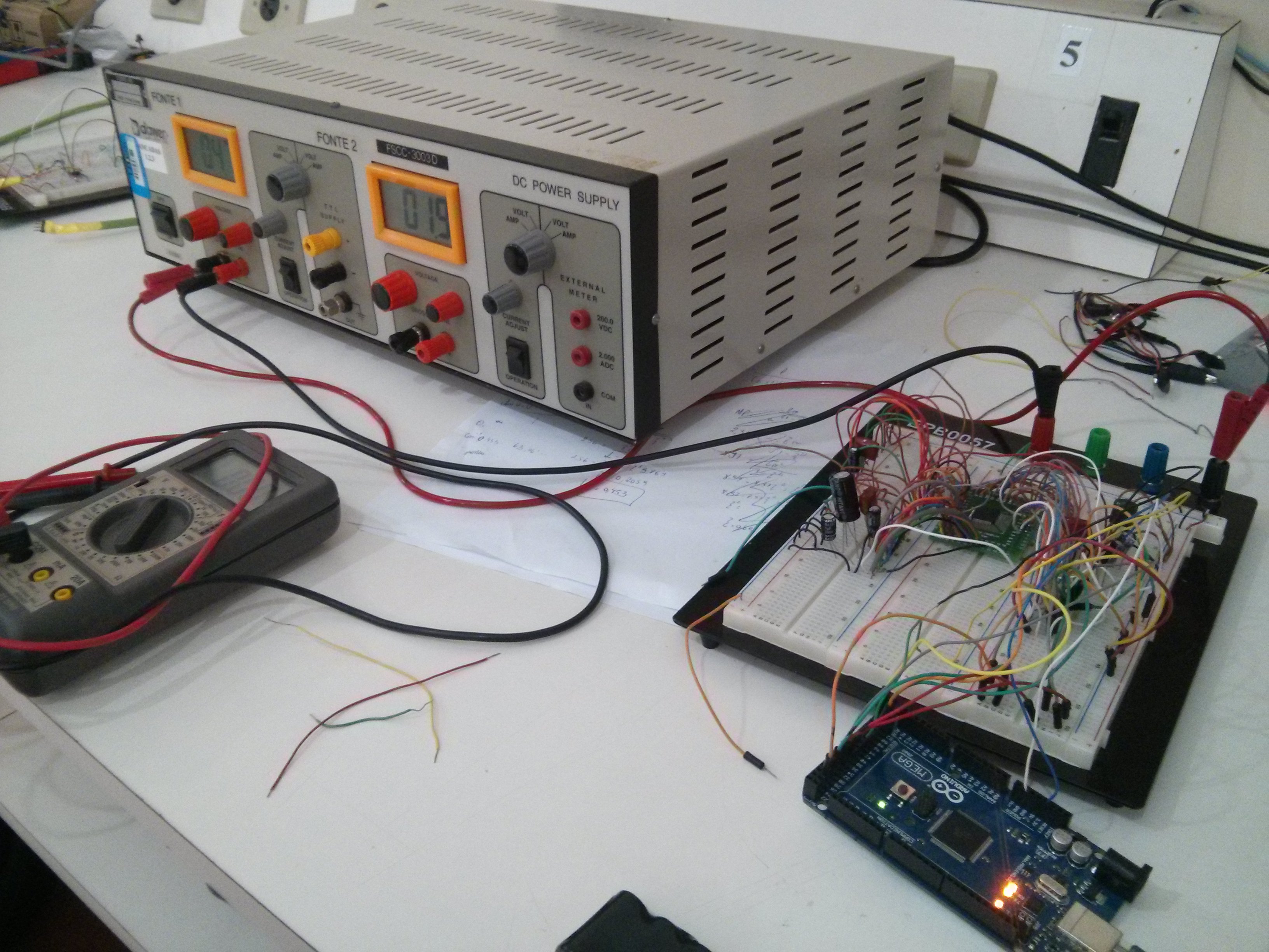
Here is a screenshot of my setup (I know it isn't the more appropriate approach, but this is just a chip validation):

Thanks

  • Hey JJ,

    The part will return channel conversions in two's complement binary. Two's complement words with leading 0xF's are generally small negative values. Have you accounted for this?

    Regards,
    Brian Pisani
  • Thanks for answering Brian!

    I remember I toyed around converting the readings from 2's complement and I had no success.
    I did it again just to be sure and maybe that's the problem.

    But I am not sure if I am doing it right:

    First, I invert all bits of my data. Then I add one bit to it.
    And finally, considering the type of data is long, I subtract 0xFF000000;

    Here's the part of my code that deal with this matter:

    channel[i] = ~channel[i];
    channel[i] = ( channel[i] | 0x00000001 ) - 0xFF000000;

    And then I just have to multiply the value by 4.5/(2^24).

    I gave it a shot and I am still unsure if it is correct (I am getting very low values now, but I can't measure a 2.5V battery I have... the readings are not right at all). I am still toying with it.

    Thanks
  • Btw, I realized that it should be "+" instead of "|"
    But values don't seem right yet. I am still checking stuff

    Thanks again
  • Hey JJ,

    What voltages are you getting for the input short measurement with your new 2's complement conversion algorithm? Also realize that you will need to divide the resulting voltage by the PGA gain setting you are using to get the correct input referred voltage.

    -Brian
  • Hey Brian!

    My PGA gain is set to 1 so that won't change my code.

    I don't know if the channel inputs interfer anything when in input short mode, but anyway... they are grounded.

    So, these are the readings I get in all channels (input short):

    Some things I noticed:

    Channel 8 NEVER has a value of 0.xxxx.

    Sometimes other channels get a 4.4xxx value.

  • Here are register values, just in case.

    Btw, arduino won't display MSBs of a word if they are 0.

  • Also, I don't get why I was having "0xFF..." values (as I shown in the first post of this topic), considering I am using unipolar supply.

    According to the datasheet, anything greater than 0x800000 is negative!

    Isn't that right?
  • Hey JJ,

    Would you mind posting a screen capture of one of your data collection SPI transactions?

    Brian
  • In reference to your last post, the data is measured as IN1P - IN1N. If IN1N has a larger voltage than IN1P, even if they are both positive voltages, the result will be negative.
  • Hey Brian, sorry for taking so long to reply.

    This is the part of my code used to acquire data:

    If you were talking about screen capture of a scope or something, I don't have it right away, but I am gonna try and see if I can make it work.

    edit: I managed to get the scope working. Pictures are in the next page.

  • Hello again Brian,

    I managed to get the scope working. Unfortunately since I don't have any kind of connector, I am using the probes (only 2 channels available) in order to get the signals.

    Yellow line - DOUT

    Green line - SCLK

    The following image shows a whole 216 bits aquisition

    The following image shows the very beggining:

  • And here is my DRDY, working as 250 SPS (as set in the register)

    And here is my DRDY when actually converting (green line is SCLK)

  • Hey JJ,

    I was hoping to see the individual bits of conversion data coming from the device. It possible to capture that?

    Brian
  • Hey Brian,

    The first two pictures I posted on this page show the individual bits coming from the device (DOUT). Isn't this what you were hoping to see?

    If not I'm sorry, can you explain in other words what you want?
    I can capture right away (scope and arduino serial monitor if needed).

    Here is the individual bits of each channel in arduino (input short mode):

    First picture: RAW BITS

    Second picture: BITS converted FROM 2's complement.

  • Hey JJ,

    I was hoping to be able to read the individual bits of one of the channels' conversions to ensure the bits are coming back as your program is reporting. Perhaps do something similar to your first image but zoom into one of the channel's data.

    Regards,
    Brian
  • Hello Brian!

    Ah I see...

    So, I checked and the bits coming from DOUT is actually the same I can read from Arduino serial monitor.

    Conversion start: (status)

    The very next 24 bits (channel 1)

    And Arduino serial monitor

    As you can see, Status and Channel 1 are correct (I didn't check the other channels).

    Do you think I should check all 216 bits as well just to make sure?

  • Brian, just so you know I won't be working on this for 3 days.
    But let me know what you think about my last post.

    I'll post here again when I get back at this.

    Best regards
  • Hey JJ,

    I'd like to see your schematic when you get a chance to post it.

    Regards,
    Brian Pisani
  • Hello Brian,

    So here is my schematic:

    I may have good news though: After checking the connections, I noticed that VREFN wasn't grounded.

    After grounding it, things looked better.

    Now I am able to measure the input voltage with more accuracy. The input short mode looks more stable, also in normal input mode grounded inputs

    gives me a very low voltage (0.000... V). And when I try to measure a 2.5V battery I have I get a 3.18V (at least it is stable).

    As you can see now things are looking better.

    In the following screenshot ALL channels EXCEPT CH6 are in input short mode. CH6 is in normal input mode, with a 2.5V ddp between IN6N and IN6P.

    So, as I said, things are much better now. I still have this offset problem though (which may be caused by wrong calculation when converting bits to voltage).

    And also CH8 is always "stuck" at this 4.49V even though it is in input short.

    This is how I convert from decimal to voltage values:

    channel[i]*(4.5/(16777215)    ----> I am dividing by 2^24 - 1

    ps: channel[i] is already converted from 2's complement.

    Thanks

  • Something I noticed: Using a power supply, I noticed that my if increase the input voltage, my output voltage displayed in arduino actually decreases.

    Where is what I'm trying to say.

    I am not sure about this but I changed my conversion formula to:

    (4.5 - (channel[6]*(4.5/(16777215) ) ) )*2

    It kinda works now but I did this without actually thinking, that's why I will double check it

  • Hey JJ,

    Glad that got sorted out. Instead of dividing by 2^24-1, you should divide by 2^23-1 since you will really only use 23 bits for representing signals and the last bit is used to represent sign. That would not account for your error though since dividing by a smaller value gives you a larger voltage. In addition, if you convert that voltage back to digital codes using your formula, you get a code larger than the full scale range of the device, so I anticipate that error is occurring elsewhere. This problem occurs for channel 8 as well, but I'm not sure why you'd get such a large value in the first place, whatever the error. I would try reading back channel 8's register to ensure that it is being written correctly.

    Regards,
    Brian Pisani
  • JJ,

    You are converting from 2's complement incorrectly. That would account for the values decreasing as the voltage decreases. Here is what you should do with negative values:

    OR the value with 0xFF000000 to "sign extend" the data to unsigned long
    Subtract 1
    NOT the bits

    You should now have a positive version of the negative voltage you converted. Then you can multiply by the scaling factor to turn it into a voltage. If you need some logic to determine which values are negative, just compare the output value to unsigned 0x00800000. If your unsigned output is "larger" than that 32-bit word, the output value is a negative number.

    Regards,
    Brian Pisani
  • Hey Brian!

    Thanks for helping me, I figured out the problem in channel eight.

    I wasn't including him in anything because in my iteration loop I stopped at channel 7. Very silly mistake!

    Btw, I tried to do what you said with negative values and it isn't working. I got the logic of it and the steps are simple, but I tried something else

    and it worked right away so I'll take a second look at the way you said in another time.

    I found this in the internet:

     You can do this by 'XORing' the data with 0x800000. Full scale positive is 0x7FFFFF, XORing that with 0x800000 would give you 0xFFFFFF. Full scale negative is 0x800000, which yields 0x000000 when XORed.

    Would it accomplish the same as you said?

    I tried this method and noticed that my voltage values were ranging from 4.5 to 9v. Actually from 0 to 9v if negative was included.

    So, I just subtracted 4.5 of my signal in order to "offset it back" to 0 again.

    Now I get -4.5 to +4.5 scale.

    Any errors in all this?

  • Hey JJ,

    XORing the data with 0x800000 is equivalent to adding 4.5 V without carrying a final overflow bit (look up "adder schematic" and you will find that a bitwise ADD function consists of an XOR and an AND which indicates carry). If this way is easier for you, then I don't see an issue with it.

    Regards,
    Brian Pisani
  • Hey Brian!

    Everything seems to be working fine. Internal signal generator, input short and normal input, etc...

    The thing is, when mesuring a battery (or even a regulated power supply) I get a ~0,38V offset for any voltage above 0,5V.
    Exemple: real value (measured with voltimeter to make sure) = 3V, the ADS gives me 2.65-2.7V.
    As you saw I have a very poor design, using a protoboard and all.

    But when I try input short mode to actually measure noise and offset, I get around 40uV.
    I thought I should get something more than that right? That seem to be just noise!

    Any thoughts?

    By the way, I never told you but I am using this to measure EMG.
    Just a quick question: I am gonna use bipolar EMG so I will have to use SRB1 as a reference electrode right? (I've already looked up and that's what it seems)
  • Hey JJ,

    Did you measure the 3 V as close to the inputs to the ADS1299 inputs as possible? I'm trying to rule out that some shunt current is dropping voltage somewhere before the input pins to the ADS1299. In addition, how are you ensuring that the inputs are staying within the conversion range of the device? Are the battery leads floating with respect to the board supplies or have you referred them in some way?

    As for the offset error, a typical value is specified in the Electrical Characteristics table of the datasheet as 60 uV so the 40 uV you are seeing is within spec. The magnitude of the noise from peak to peak should be significantly smaller than that.

    You would use the SRB1 pin in a unipolar configuration where you want to measure all electrodes with respect to a single electrode. In a bipolar configuration, you'd want to measure some difference between the positive and negative inputs.

    Regards,
    Brian Pisani
  • Hey Brian,

    So the problem about the offset was what you said: the leads were floating with respect to the board supplies.

    I grounded the battery (negative lead) to the negative of the power supply and that worked.

    I'm using a battery (it's 2,2V now) and I'm getting the following:

    As you can see there are some spikes. I've implemented a moving average to "cut" them out and it works perfectly.

    But I am not sure the cause of it...

    So I tried to implement a passive 60Hz filter but it didn't work (I gave it a shot even though it doesn't seem to be a 60 Hz power line noise problem).

    Should I worry about them or they are just a result of my whole protoboard circuit?

    Another question, if my PGA isn't working properly (high or low voltages, doesn't matter) then I should take a better look into the common-mode range?

    Here are some tests (I used 2 power supply - one grounding INN and the other actually giving voltage to INN and INP).

    GAIN - VOLTAGE

    1 - 2.25 (correct)
    2 - 3.03
    4 - 3.64
    6 - 3.90
    8 - 4.05
    12 - 4.21
    24 - 4.37

    1 - 0.107 (correct)
    2 - 0.16
    4 - 0.19

  • Hey JJ,

    The PGA on the ADS1299 is a true differential amplifier. This means that the positive and negative input voltages will get amplified with respect to the common mode. If you ground the negative input and have a gain higher than 1, the negative PGA output will rail negative since it "wants" to go lower, so to speak. You are instead going to want to measure differential voltages are whose common mode voltage is near analog mid-supply since this will give you the greatest range.

    In addition, the PGA is not a true RRIO amplifier and so placing the negative input at AVSS even with a gain of 1 may produce erroneous outputs. If you are looking for a convenient source for an actively driven mid-supply voltage, the BIAS amplifier on this device can be configured as such using register settings. You can tie the negative end of your battery to the BIASOUT and connect that to INxN then you will be neared to having a mid-supply common mode.

    Regards,
    Brian Pisani