This thread has been locked.

If you have a related question, please click the "Ask a related question" button in the top right corner. The newly created question will be automatically linked to this question.

Choose an efficient regulator switch for dac7563.

Other Parts Discussed in Thread: OPA140, DAC7563, OPA2140, TPS7A49, TPS7A30, LM7301

Hi, I have the next DAC7563 design. I've got 3 dac7563, a total of 6 DACs with 6 opa140 to adapt the output signal from 0..5 volts to -5..+5 volts.
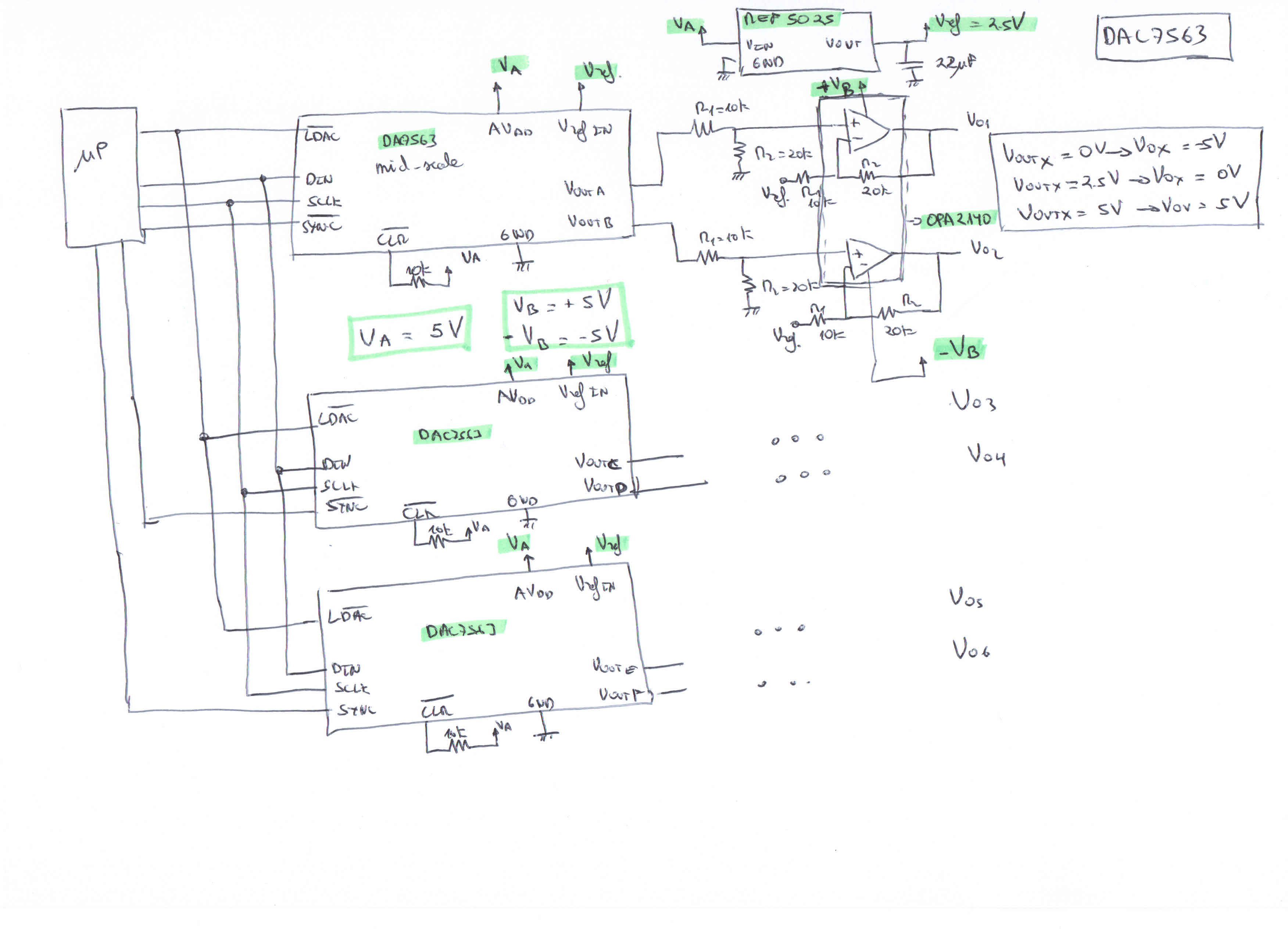
I need to power supply the 3 dacs7563 and the 3 opa2140 and I'm not sure the most efficient way. I dispose of a source of 12 Volts@1A(max) and I need the following voltages:

1º.- Va = +5 Volts to feed the 3 dac7563 and REF5025.

2º.- With an REF5025 I achieve the voltage reference for the 3 dac7563, but I don't know if one REF5025 is enough to power supply the 4 DACs and the resistors R1=10k wich is part of the opa2140o r I need three of them.


3º.-I though in use the ultralow-noise TPS7A49 (to get ultralow noise: +Vb = +5V) and TPS7A30(to get ultralow noise: -Vb = -5V) to feed the opa2140 ICs.

But my big headache it is to choose an efficiently power switch to convert from 12Volts@1A(max) to 5Volt to feed the DAC7563 and REF5025 and another power switch to convert from 12Volts to +5V and -5V to feed the opa2140.

Could anyone help me to choose this ICs?


  • Howdy Oscar,

    You can calculate the reference current requirment of the dac7563 devices with the given 'Reference input impedance' given on page 7 of the DS.  For an external Vref of 2.5V, and a gain of 1 the current requirement is calculated as ~15uA, while a gain of 2 produces an external current requirement value of 29uA.


    Since this is a buffered device, the DAC output obtains source current from the positive supply rail, AVDD.
    As for the operational amplifier circuit you derived in the attached circuit, current across the 10k resistor attached to the reference source is calculated as:

    I@10k= (2.5 - .667*Vdac)/10k


    The maximum amount of current from the reference is at DAC code 0, this would produce a current of I=2.5/10k = 0.25mA.  Since you have three of these OPA circuits, the maximum current required from the reference would be 0.75mA + 3*29uA.  The REF5025 is capable of sourcing 10mA, which is plenty for the given circuit.


    I would recommend that you ping the Power Management forum for help with regulator and power circuits.  The forum is found by clicking the Support forums button found above.

    Best Regards,
    Matt

  • Hi Matthew,


    I have two questions more:

    1º.- My six outputs from the opa140 are going to feed the input of a system with an impedance of about 2.5Kohms. This input is the set point speed of thrusters. The speed of the thrusters has a dead zone from -5V to -4.75V and from 4.75V to 5V so I don't mind not to achive -5V and 5V.

    I am feeding the op140 with V- = -5V and V+ = 5V. According to the datasheet of the opa140 (Page 4: OUTPUT VOLTAGE with RL = 2Kohms):

    Vout(min) = (V-) + 0.35 [-5 + 0.35] = -4.65V
    Vout(max) = (V+) - 0.35 [+5 - 0.35] = 4.65V

    Then, What do I have to do to get at least a range in the output -4.75 Volts to 4.75 Volts?

    V+ has to be at least 5.1V and V- at least -5.1V. Is it correct? Or with V+ = 5V and V- = -5V could be enough?


    Thank you so much. Best regards.
  • Howdy Oscar,


    You additionally need to verify that the input voltage range is acceptable.  In the datasheet the, VCM, the common-mode voltage range is defined as:


    Notice that a V+ value of 5V limits the maximum input voltage to (5V - 3.5V = 1.5V)!  Since the DAC output sees a voltage divider of (2/3)Vdac, you would at least need a V+ supply of V+=3.33V + 3.5V = 6.83V. 

    A good rule of thumb is to always check the common-mode voltage range of the op amp when designing circuits in the non-inverting configuration.

    For you to meet your constraints you would need to increase V- and V+ accordingly.

    For future questions related to op amps I would recommend you to post in the following forum:

    https://e2e.ti.com/support/amplifiers/precision_amplifiers/


    Best Regards,

    Matt

  • Hi Matt,

    I know you aren't in charge of amplifiers but I would like to understand completely how to choose correctly the op amp in any type of application and I have a small doubt.

    For exmaple in the op amp LM7301 the datasheet doesn't metion the maximum and minimum Input Common-Mode Voltage Range. Then If I use the LM7301 instead of the opa140. How can I be sure my design is correct?

    Thank you so much. Best regards.

  • The LM7301 can be driven by voltages that exceed both power supply rails, thus eliminating concerns over exceeding the common-mode voltage range.

    All common-mode input specs are provided in page 3, 4, 5 of the DS, just search for the parameter Vcm.

    For instance, page 3 of the datasheet gives a typical Vcm range of -0.1 to 5.1V for a V+ value of 5V and a V- value of 0V.

    Matt

  • Thank you very much. I understand perfectly.
