This thread has been locked.

If you have a related question, please click the "Ask a related question" button in the top right corner. The newly created question will be automatically linked to this question.

ADS1247 Configuration registers automatic write problem.

Other Parts Discussed in Thread: ADS1247, ADS1248

Dear All,

In my analog input application i am using ADC ADS1247 interfaced with PIC32mx575f512l ucontroller. Everything is working fine. my readings are ok. 

but now i am facing a problem for automatic register change while running.

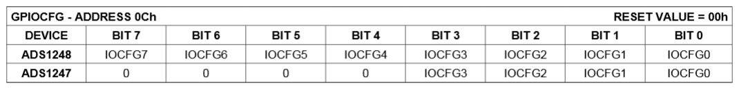
my problem is GPIO register value change automatically. i am never writeing its value.

my firmware is as below and inside you can see i am never write GPIO register but still its changing to (GPIO0 = 0x3F).

Please help as soon as possible. 

SpiWriteByte_ADC(ADC_no, 0x40); //4: WRITE 0: ADDRESS SYS0
SpiWriteByte_ADC(ADC_no, 0x03); // = total data-1 (no. of bytes to send -1)
SpiWriteByte_ADC(ADC_no, RTD_CH); //CH1 [AIN0=+ and AIN1=-]
SpiWriteByte_ADC(ADC_no, 0x00); //0x00 BIAS VOLTAGE OFF
SpiWriteByte_ADC(ADC_no, 0x30); //00:EXT REF 30: int ref on board //33 INT REF+TEM DIODE
SpiWriteByte_ADC(ADC_no, 0x42); //0x41; //16 gain//62--64 gain//gain =4, 20SPS

SpiWriteByte_ADC(ADC_no, 0x4A); // 4: WRITE A: Address IDAC0
SpiWriteByte_ADC(ADC_no, 0x01); // Length = total data -1
SpiWriteByte_ADC(ADC_no, 0x0B); //DRDY & Current value selection - 08 = no current
SpiWriteByte_ADC(ADC_no, 0x3F); //current channel select = 500uA = 0x0C , 250uA = 0x0B

void SpiWriteByte_ADC(unsigned char ADC_No, unsigned char byte)

{

    unsigned char j = 128;

while (j > 0)
{
        SET_SCLK_ADC_1;  
        Delay2us(1); 
        if (byte & j) SET_MOSI_ADC_1;
        else RESET_MOSI_ADC_1;
        RESET_SCLK_ADC_1;
        Delay2us(1); 
        j >>= 1;


}

}

  • Krunalkumar,


    I could be wrong, but to me it looks like you're reading from the wrong register. There isn't any reason that the device should change what is in the register without a proper read or some sort of reset. You show the write code, but you don't show the read code.

    Looking at your write to IDAC0, it looks as if you're trying to write 0Bh and 3Fh starting at address 0A. There are several bits that aren't used in the ADS1247, but are used in the ADS1248. It's also not clear what register you are having a problem reading back. Is it the GPIOCFG register (0Ch)? If so, the first nibble should always be a 0.

    I'd start by checking the addressing of the registers, and then I'd check the read back of the register by reading all 14 bytes in one shot. This would determine both the data and the order of the register data.

    If this doesn't pan out, I'd start checking the timing of all of the SPI communications. Start with the polarity of the clocks, the phase of SCLK and the speed of SCLK.


    Joseph Wu
  • Dear Sir,

    We dont have problem of reading GPIO register. But it value is automatically changing is out problem. because of GPIO register value change i will get current source 3mA instead of 250uA which i have configured.

    Let me explain in more detail:

    In My application i have made 8 Channels Analog Input card using ADS1247 for RTD input type. my sampling time is 20SPS and i have set READ data once in ADC for Single conversion mode. i am Selecting my mux and configure adc as above code and give command for conversion start. every thing is working fine. reading are ok in run condition. but before 3 day we foung one problem. my actual reading is 0 deg and it is jumped to 400 Degree and after power off and ON cycle readings are coming back to 0 Degree. In hardware we found every component is ok no dry soldering or any other issue. so that we have checked firmware to investigate the problem. for that we have read all Registers of ADC after configuring it. all registers are write ok. we are not writing GPIO registers in our code. Initially they are at 0 but after some time we found value of GPIO0(Address 0x0C) is 63. and we have checked our readings are disturbed. so that we have measured current source is rised to 3 mA from 250 uA. so of that reason out readings are showing wrong. Please help as soon as possible. if any other details are required that let me know.

  • Krunalkumar,

    I think that I understand. To make sure, you're saying that somehow, the GPIOCFG register (OCh) gets configured as an output and this forces more current out of one of the pins used for excitation current. The extra current out causes a large error in the measurement. By cycling the power, the error goes away because the GPIO becomes reset and correctly re-configured as the analog input.

    I would note that the ADS1247 should not read 63d (3Fh), it could read 15d (0Fh) because the first nibble should be 0. Note the register configuration from the datasheet:

    As I mentioned in my last post, the part will not just change configuration unless it receives a command to do so or there is a reset (either from the reset command, reset pin, or from a power down of the part). I think you should still read back all the registers and report back the resulting values to make sure that they are set the way you think they are. At least you will know how the part is configured when this problem is happening. Do you know what the last command issued is when this problem occurs?

    I believe there are two possibilities. First, would be that the code accidentally sent the wrong command at some point to change this register. I've seen cases where the wrong command was buried in a section of code that isn't often used and this became hard to find.

    The second possibility would be noise in the digital communication. The most common issue would be noise in the SCLK line. If this noise is high enough, the device may receive extra SCLK pulses when the SCLK was not sent by the master. This could affect either the command or the transmitted data. I've seen where small amounts of parasitic capacitance from SCLK to another digital line created these types of error. You could attach some modest amount of capacitance onto the SCLK line to see if it helps clear up this issue. You'll need an oscilloscope to test this. Too little capacitance won't help, and too much will disrupt the SPI communication as well.

    Joseph Wu

  • Dear Sir,

    I have checked that if i am writing manually 63H in GPIOCFG then it is reading back to 63H. first nibble in not zero in that case.

  • Krunalkumar,


    One useful tool would be a logic analyzer that can trigger on different SPI communication events. In this case it might help to trigger off of any WREG in the communication. This might be the best way to track down this problem.

    Again, I'd read back all registers to make sure that there aren't any other random changes in the register settings. I really think the source of this problem is an errant SPI communication that does a WREG when it shouldn't. Registers should not change during operation without the WREG command.


    Joseph Wu