This thread has been locked.

If you have a related question, please click the "Ask a related question" button in the top right corner. The newly created question will be automatically linked to this question.

ADS1248 - Missing S1?

Hello all,

See below an image of the ADS1248EVM. Most images i see there is a red switch at the top next to the chip that says 104. However this one does not have it. I thought this was necessary to use an external reference. 

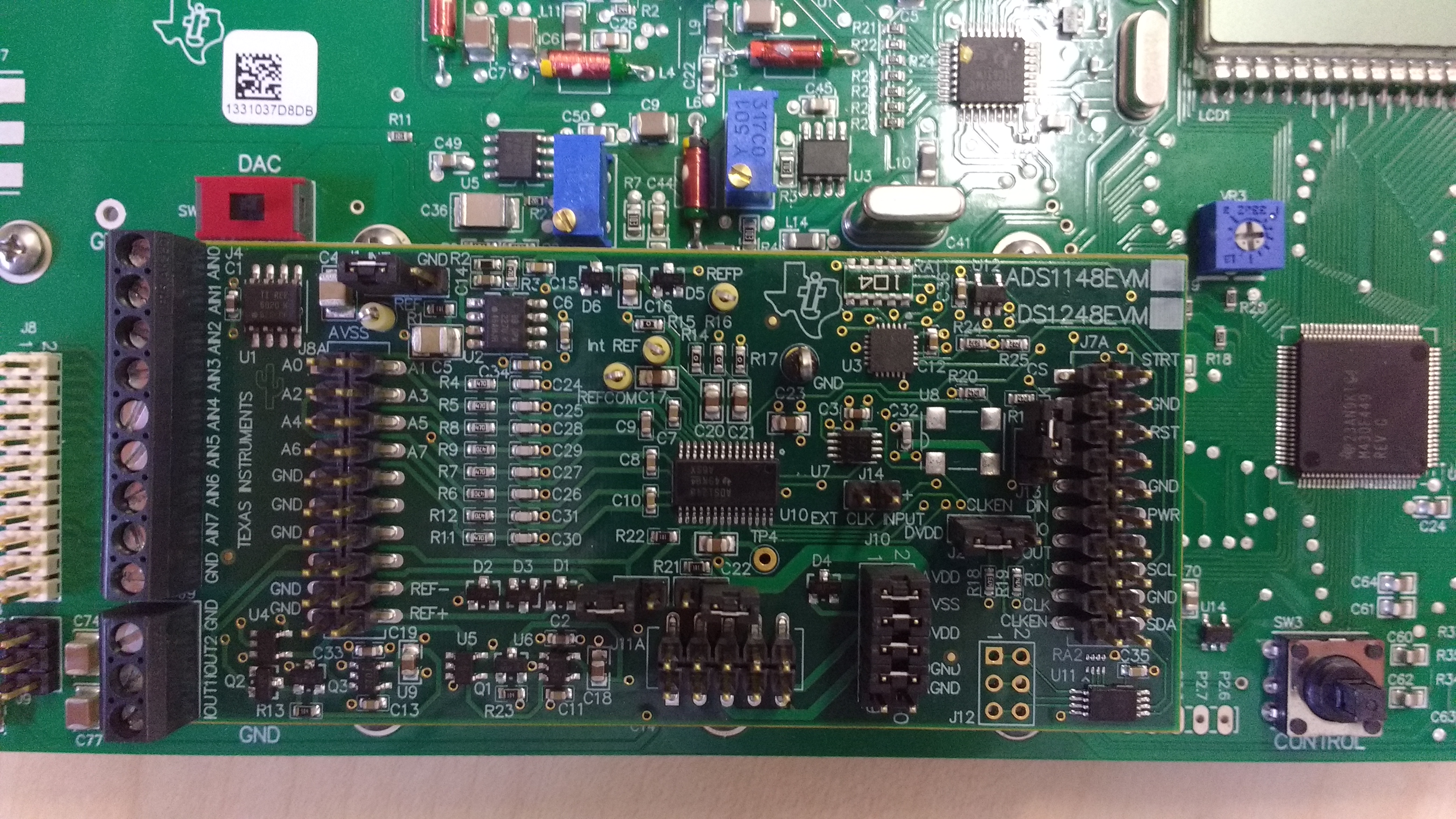
Another thing i noted is that some documentation sees to also conflict with the names on the board. I.e. which pin should i be using for inputting a reference. Is it the Ref-+ pins to the left of D1-3.

Any help would be appreciated. Thank you,

Steven

  • Ok the switch isn't necessary for inputting a reference but I need to change J1 position to the 2-3. Would this then allow the previously highlighted Ref-+ to be used as an input for reference?

    Steven
  • Steven,


    Yes, switch S1 was taken out. there was an initial board design with the S1 switch that allowed the reference to go to AVDD. After characterizing the part, the product line decided to change the allowable VREF maximum as there was some issues running VREF at AVDD. I had thought the schematic was updated, so that's something I'll have to check into.

    J1 is used to connect the REF1P inputs when the supplies are bipolar (+/-2.5V). It's described in Table 5 on page 6 of the ADS1248EVM user guide.


    Joseph Wu
  • Steven,


    The schematic is in the ADS1248EVM User's Guide. The Rev A schematic is shown first on page 31, the Rev B schematic is second on page 32. Since there were so many Rev A boards out, it made sense to keep it in the user guide.

    I checked with a colleague to find out.

    Joseph Wu