This thread has been locked.

If you have a related question, please click the "Ask a related question" button in the top right corner. The newly created question will be automatically linked to this question.

ADS1259 Qquestions

Other Parts Discussed in Thread: ADS1259

I'm am looking for a quick turn for a customer I have aggressively supported.

My question is: if I am sampling at say 1200SPS or at the 14.4KSPS is it realistic to measure a low frequency sinusoid (around 1KSPS) with the ADS1259?  My guess is yes, but I am guessing that there is a slew rate limitation?

Probably the DR bits set to 5 for 1200SPS, or 0 for 14.4KSPS.

My real question is probably more about aperture window.  I am guessing that the window of sampling is smaller at the higher sample rates.

If you look at figure 54, I understand that one, but why would one toss the sample during transition...isn't that what a filter does?  Just want to be sure I am not missing something.

At the moment I am just software polling the data-ready bit which is not all that accurate and I suspect I am missing samples due to that polling. 

The one peculiar thing I am seeing is that sometimes I get two or three samples that are the exact same value in a row.  Even if I run the

ADS1259 with DR=0 (10SPS).  In my software I also post a number for each sample indicating whether or not our loop to test for data ready has run at least once (meaning it has detecting data ready inactive), and doing so I still get duplicate values.

Since my software is polling the data ready bit in the ADS1259 register I can understand if we miss a sample here or there.  At even the 10SPS data rate every once in a while my software will miss the data ready going inactive.

In the software I am simply getting the ADC value and writing to an array.  After 1024 samples, it then writes it all to a file.

I am running the SPI interface clock at 100KHz.

what might cause one to read out duplicate A/D values?

  • Hi John,

    Let me answer your questions in order...

    JOHN CARRARA said:
    My question is: if I am sampling at say 1200SPS or at the 14.4KSPS is it realistic to measure a low frequency sinusoid (around 1KSPS) with the ADS1259?  My guess is yes, but I am guessing that there is a slew rate limitation?

    Yes! Nyquist theorem always applies, so as long as you sample the input signal 2x or more times faster than the input signal's frequency, you should be able to detect the 1 kHz signal after performing an FFT of the sampled data.

    Regarding slew rate limitations, there is no op amp or PGA gain stage inside the ADS1259. The input signal is simply charging a very small sampling capacitor. The input source ought to have a low output impedance to be able to "fully" charge this capacitor before it is sampled (A capacitor is never really "fully" charged, but in this case I mean that the difference between the sampling capacitor voltage and input signal voltage is negligible). The -3 dB bandwidth of the ADC's input (i.e. RC LPF) will be much higher than the ADC's data rate. This is usually NOT an issue unless the application is undersampling a much higher frequency signal with a lower sampling rate. Note that it may be necessary to use an external buffer with the ADS1259 to prevent gain errors resulting from not "fully" charging the sampling capacitor. Most any op amp should be able to handle a 1 kHz signal without slewing.

    The ADS1259 will attenuate signals based on the digital filter's SINC frequency response. For minimal attenuation use the faster data rate setting. At 14.4 kSPS, the digital filter's -3 dB filter bandwidth is 2.93 kHz (refer to Table 4 in the ADS1259 data sheet).


    JOHN CARRARA said:
    If you look at figure 54, I understand that one, but why would one toss the sample during transition...isn't that what a filter does?  Just want to be sure I am not missing something.

    The SINC filter behaves much like a moving average filter... If the moving average filter averages the last 2 conversion results, than you would need to collect at least two results for the average value to be correct. This is essentially what Figure 54 is indicating; however, note that the "number of averages" changes based on the ADC's data rate, as shown in Table 10. This is due to the digital filter being a cascade of SINC5 + SINC(1/2) filters.


    JOHN CARRARA said:

    The one peculiar thing I am seeing is that sometimes I get two or three samples that are the exact same value in a row.  Even if I run the

    ADS1259 with DR=0 (10SPS).  In my software I also post a number for each sample indicating whether or not our loop to test for data ready has run at least once (meaning it has detecting data ready inactive), and doing so I still get duplicate values.

    Since my software is polling the data ready bit in the ADS1259 register I can understand if we miss a sample here or there.  At even the 10SPS data rate every once in a while my software will miss the data ready going inactive.

    In the software I am simply getting the ADC value and writing to an array.  After 1024 samples, it then writes it all to a file.

    I am running the SPI interface clock at 100KHz.

    what might cause one to read out duplicate A/D values?

    If you're measuring a DC signal, I would expect you to see a Gaussian distribution of output codes with some output codes repeated. However, if this distribution is skewed or if you are consistently reading out duplicate codes than likely there is a software issue somewhere...

    First, make sure to retrieve the data using the "RDATA" command. This is required any time it is possible for new conversion data to update while reading out the old conversion data.

    Next, I would probe the SPI communication to make sure the SPI timing is correct and verify that the software is indeed waiting until another conversion occurs before reading out data. It could be that the software is reading a duplicate result within the same conversion cycle. I could see this occurring for the slower data rates.

    Another thing to check would be how the data is being handled in software. Often I've seen invalid data types being used to store the data, or the 24-bit data is not correctly sign-extended into a 32-bit data type.

    I'd be glad to review any logic analyzer/oscilloscope screens shots of the SPI communication, or code snippets if your customer is willing to share!


    Best Regards,
    Chris

  • Chris,

    Your timely response is very much appreciated.

    Thanks,

    John

  • Hi John,

    Certainly; please let us know if you get any follow-up questions you'd like addressed!

    Best Regards,
    Chris
  • Chris I certainly appreciate your help.

    Comment if you have the time available.

    Thanks again.


    Customer's follow-on


    Pseudo code:

    RESET

    delay 100mS

    SDATAC

    STOP

    Send configuration to registers

    START

    for ( 0 to 1023 )

    {

    Wait for Data Ready (polling the ADS1259.Config2.DRDY

        bit looking for it to become '0')

    RDATA

    Stuff the result sample into a buffer

    }


    This might not work correctly(?) because now it is sampling continuous and maybe the DRDY bit cannot be polled at the ADS1259.Config2 register?

    Maybe I need to run in Data Read Stop Continuous Mode only?

    I thought that once the falling edge of the SPI clock would cause it to take another sample and DRDY would go inactive?

    In the final design I plan to watch the data output bit (DRDY) and then run in continuous mode (discussion on page 30 of datasheet)

  • Hi John,

    I don't see any problems with that software routine, but let me try to verify it and get back to you. Regarding the new questions:


    JOHN CARRARA said:

    This might not work correctly(?) because now it is sampling continuous and maybe the DRDY bit cannot be polled at the ADS1259.Config2 register?

    Maybe I need to run in Data Read Stop Continuous Mode only?

    I thought that once the falling edge of the SPI clock would cause it to take another sample and DRDY would go inactive?

    In the final design I plan to watch the data output bit (DRDY) and then run in continuous mode (discussion on page 30 of datasheet)

    I'm looking into this...According to the data sheet ("DATA READY" section on pg. 28), you should be able to poll the DRDY bit in the CONFIG2 register by putting the device into the "stop read data continuous" mode. You put the ADS1259 into this mode in your pseudo-code when you sent the "SDATAC" command, so this ought to be fine.

    What is unclear to me is what happens to the DRDY register bit after you start sending SCLKs. According to the data sheet, the /DRDY signal will return high (when operating in gate control mode, i.e. the device is continuously converting). Therefore, it would seem that the DRDY register bit would also go high before you were even able to read it. If this is the case, than the only way to be able to poll the DRDY register bit would be to operate the device in "pulse control mode" and the pseudo-code would need to look like this:

    RESET

    delay 100mS

    SDATAC

    STOP

    Send configuration to registers (set PULSE bit = 1, and tie START pin low)

    START

    for ( 0 to 1023 )

    {

    START

    Wait for Data Ready (polling the ADS1259.Config2.DRDY

        bit looking for it to become '0')

    RDATA

    Stuff the result sample into a buffer

    }


    I would generally advise monitoring the /DRDY pin so that you can implement a software interrupt to read ADC data. As long as the processor is fast enough, this prevents the loss of ADC data and may prevent some of the timing problems that occur when reading data while the next conversion is finishing.


    Best Regards,
    Chris

  • Hi John,

    I checked with the digital designer and he confirmed that the ADS1259 must be in pulse convert mode in order to use the DRDY register bit for polling. I'm sorry that this is not clear from the data sheet!

    Best Regards,
    Chris
  • Chris,

    Many thanks. Very helpful and timely.

    I'll see the customer tomorrow.

    John

  • Chris, I'll try and post files Monday.

    Some customer feedback after my visit:


    I am 100% certain that duplicate samples are actually coming from the ADS1259.


    ----------


    Here is a brief/exhaustive summary of what I have done.  I am at a dead stop and for the life of me cannot figure out what is going on with the ADS159.  I am out of scenarios to chase down.  Everything I have chased since our last meeting has turned out to be OK.  I have even modified software to take glitches in the data into consideration.


    -


    What I need to know is what might cause this.


    I suspect it is something odd with the ADS1259 state machine. It has to be some unpublished issue or restriction of some kind.


    Is there any sort of other command that would behave similar to the RDATA that might give us a duplicate sample output somehow?  It seems very unlikely that it is a bogus START command or RREG sort of command.


    ----------


    I have attached a bunch of data in a zip file.  Here is a description of each of the files.


    -


    out.txt   -  resulting A/D data along with register setup.


    a) first 10 lines are the register values of the ADS1259 just before we begin sampling.


    b) lines 11 to 110 are the samples.

    b.1) first column is the A/D value

    b.2) second column is the software measured time (mS) between samples.

    b.3) third column, if not zero, indicates that drdy became valid within two CONFIG2 reads.


    c) Lines 111 to 126 are the overall statistical data.  Note, we are observing a 0.1Hz triangular waveform at the input.


    -


    out.xls


    a) Illustrates a plot of the A/D data in out.txt.  Note that the sample timing seems reasonable relative to the waveform (i.e. the duplicate samples are occurring at the right timing intervals so it is highly unlikely (not possible) that two samples are being read out one right after the other or a START command is missed or anything of that sort.


    b) Note: at about -8000000 the input amplifier is railing and makes sense on the plot.


    c) You can see duplicate samples at 10, 27, 40, 80, 85 and 98.


    NOTE: the location of duplicates is never the same from run to run.  Out of 100 samples there is at least one or more duplicates that occur.


    -


    spilog.txt  - all the gory SPI software sequencing


    a) if you search for "AS_Opcode_Write:  0x09", this is a START command

    to ADS1259.


    b) if you search for "AS_Data_Read:", this is the function that performs

    the RDATA command (RDATA not shown).  The line just before it is the

    function that actually performs the read.


    c) "AS_Data_Read:" and "SPI_Data_Write_Read:" lines report the resulting

    RX_BUF data received.


    Both of these functions are "blocking", meaning nothing more happens

    until they complete.


    d) "AS_Data_Ready_Wait: 1" indicates that the software is now waiting

    for a data ready from the ADS1259.


    The "*AS_Data_Ready_Wait:" the first value reported is a loop count

    followed by the RX_BUF data.


    Bottom line for this file is that all of it, in my view looks very

    reasonable, you don't see, for example a weird change in the status byte

    being read back to determine the drdy state, for example.  It all looks

    reasonable.


    -


    Scope waveforms of the SPI bus:


    a) the scope is triggered at each sample until a duplicate sample is

    detected.

    b) for each trigger a page/screen of data is captured using the scope.

    c) Color coding of the SPI data

         Yellow - SPI data from ADS1259 (MISO)

         Red    - SPI chip select

         Green  - SPI clock

         Blue   - SPI data to ADS1259 (MOSI)


    SCRN1726.BMP - sample before sample in SCRN1725.

      page  9 of 11


    SCRN1725.BMP - sample just before duplicate sample.

      page 10 of 11


    SCRN1724.BMP - duplicate sample.  At this point scope triggering stops.

      page 11 of 11


    Zooming in on this data, the commands being sent to the ADS1259 look

    good and the data coming back, other than the duplicate sample, appear

    good too!


    -


    ----------


    NOTE: in all cases the DR=0 or 10SPS for all data.


    ----------


    1. I recorded all SPI transactions from software to a file and they all

    look good.  All appear very good and consistent.  I don't see any bogus

    values or strange data...the data in all register and A/D data all look

    pretty good.


    All this data is found in the spilog.txt file.


    1.a. The software now waits for two valid drdy active bit reads before

    reading the A/D sample.  If there are data glitches this would root it

    out.  Adding this did not seem to improve the duplicate sample situation.


    1.b. I was thinking that perhaps I have a software or fpga firmware

    problem.  After printing out all transactions, I am convinced that it is

    neither a software or fpga firmware issue.  I made the initial

    assumption that it was, and spent several days checking everything and

    to my surprise nothing has shown up in this area.


    -


    2. I now have software setup so that it issues a pulse out the printer

    port for each sample received up until a duplicate sample is received.


    This "trigger" signal is sent to the oscilloscope that is monitoring all

    the SPI lines.  The scope will capture 1 page (i.e. 1 window) per

    trigger pulse.


    Looking at the scope data, when triggering stops and I scroll back

    through the windows, the last two SPI data are indeed exactly the same.

      Stuff leading up to the two duplicates is pretty much the same.


    -


    3. We monitor the supply voltage at the A/D and it never goes below 4.92

    volts, ever.  We have a micro- coaxial connector right at the supply so

    that we can very precisely measure any glitches or ripple...this goes

    directly to the scope.


    -


    4. Data, "out.txt"


    The signal going into the ADS1259 is a 0.1Hz 20Vpp triangular waveform

    (which is attenuated 1/4 to the maximum input range of the ADS1259)


    This file shows three columns: A/D value, time between sample reads, and

    if the loop happens to not pause (i.e. wait for drdy) long enough before

    the next sample read.


    4.a. I suspect the drop in time between samples is likely due to time

    the CPU spends writing to compact flash.


    -


    5. In software I have also added the condition that when a START command

    is issued, the drdy must go inactive for at least two register reads

    before we begin to watch for a drdy active.  And, the drdy must be

    active for at least 2 CONFIG2 reads in order for the software to be

    convinced that the drdy is actually valid.  This eliminates bogus

    validity that might occur due to a glitch on the MISO data line.


    What I have noticed is that the drdy immediately goes inactive upon a

    START command, which one would expect.


    -


    6. I tried issuing bogus START commands like every fifth sample attempt

    (assuming we were off by one bit shift for example) and the result was

    that the software just sat waiting for the drdy inactive and then active

    which never comes.


    -


    7. All SPI data is passing across the ADUM5401CRWZ and the delay from

    SPI_CLK to MISO on the un-isolated side is very small relative to the

    frequency of data transmitted.  We are using a 100KHz clock at the moment.


    -


    8. SPI clock.


    NOTE: we are using SPI mode 1.  Both MOSI and MISO change on the

    rising-edge of the SPI clock.


    8.a. At SPI_CLK = 400KHz, still see duplicate samples.


    8.b. At SPI_CLK = 50KHz, still see duplicate samples.


    8.c. At SPI_CLK = 10KHz, still see duplicate samples.


    8.d. Changed chip select mode from auto-buffer to software and then

    observe many more repeat samples.  The timing from CS active to SPI

    clock edge is larger, and same with last SPI clock edge to CS inactive.


    See S100KHz_Software_Controlled_SPI_CS.xls


    The auto-buffer mode is where we stuff many bytes into the FIFO and then

    the SPI hardware automatically wraps the CS around that group of bytes

    transferred.

  • Hi John,

    Sure, I'll take a look at the data as soon as you get a chance to upload it!

    Let me know if E2E gives you any problems with attaching the file. You may also email it to me via pa_deltasigma_apps<at>ti.com

    Best Regards,
    Chris

  • Hi John,

    Sorry for the delay. I've been looking through the data and I admit I'm a bit stumped on the problem myself. I don't see anything wrong on the oscilloscope screenshots or the SPI traffic log. At this point I'd like to recommend some additional tests to try. Meanwhile, I'll see if I can replicate the behavior with the ADS1259EVM.

    First I'd try a similar test without the digital isolation to see if this corrects the issue. I have seen odd SPI behavior go away after removing the digital isolation device. (By the way, when probing the SPI communication, was the oscilloscope and logger monitoring the ADC-side or MCU-side of the isolation?)

    One thing that stands out as odd to me is the following:

    JOHN CARRARA said:

    8.d. Changed chip select mode from auto-buffer to software and then

    observe many more repeat samples.  The timing from CS active to SPI

    clock edge is larger, and same with last SPI clock edge to CS inactive

    Increasing the /CS to SCLK delay should only help the communication, not make it worse - is this really the case? The timing requirements do call for a minimum 50ns delay between the /CS falling edge and the SCLK rising edge. I would try controlling /CS via a GPIO and increasing the delay before sending SCLKs to see if results improve.


    Another thing to try would be to change the data and see if the duplicate data occurs more often or if it goes away.

    Finally, if the ADS1259 is operated in continuous conversion mode, does this problem still occur?
    (FYI: The digital designer did followup with me on the DRDY bit polling issue... He said that the /DRDY pin behavior may change when the device is in SDATAC mode to make it possible to poll the register for the DRDY bit during continuous conversion mode. I'll double check this on the ADS1259EVM too.)


    I think the test and software procedure is valid - it's hard to see how any timing issue would produce a duplicate data result when the ADC conversion is restarted after each result. I'm hoping that one of my suggestions above will help us narrow in on a possible cause. Also, I'll start look at this on my end to see if it can be replicated.

    Thanks and Best Regards,
    Chris

  • Hi Chris,

    John has been working on our behalf.

    We have removed the isolator and we get the exact same results.

    I don't understand what you mean by the following two statements:

    i) "Another thing to try would be to change the data and see if the duplicate data occurs more often or if it goes away."

    What data do you mean exactly?

    ii) "Finally, if the ADS1259 is operated in continuous conversion mode, does this problem still occur?
    (FYI: The digital designer did followup with me on the DRDY bit polling issue... He said that the /DRDY pin behavior may change when the device is in SDATAC mode to make it possible to poll the register for the DRDY bit during continuous conversion mode. I'll double check this on the ADS1259EVM too.)"

    What do you mean exactly? How do we implement this exactly? It sounds contradictory.

    -

    We could really use some help and advice here. We are running short on time and really need to get to the bottom of the duplicate sample issue. Outside of this issue the ADS1259 is operating really good. However, when everything meets the datasheet specifications, this leaves us to hunt for something we believe the person who designed the digital section of the ADS1259 could very quickly give us some insight as to possible scenarios which might result in duplicate sample readouts.

    More about our setup:

    a) Register configuration:

    config0=0x25: spi=1 rbias=1 id=2
    config1=0x80: delay=0 extref=0 sinc2=0 chksum=0 flag=1
    config2=0x90: dr=0 pulse=1 syncout=0 extclk=0 drdy_b=1
    ofc0=0x00
    ofc1=0x00
    ofc2=0x00
    fsc0=0x00
    fsc1=0x00
    fsc2=0x40

    b) the duplicate samples are coming from the ADS1259 as we see the data directly on the 'scope. You have images of at least one example.

    c) we are operating in Data Read in Stop Continuous Mode.

    d) At the moment we are logging everything related to the SPI transactions and so we have confirmed operations over many many transactions. You have an example of such log too I believe.

    e) we are inputting a triangular waveform (0.1mHz) generated by a Keithley 3390. This waveform goes through a voltage divider with a filter cap, and then through a precision voltage buffer to the ADS1259. It seems extremely unlikely that the output can hang for 100mS at precisely the same voltage (i.e. < 300nV). We tried changing the frequency to 0.2mHz and get similar duplicate sample behavior.

    f) we believe we are meeting all timing constraints as described within the data sheet. The SPI timing is hardware controlled.

    g) The commands flow as follows (simple software loop):

    g.1. START.

    g.2. we poll the CONFIG2.DRDY bit using the RREG command (three bytes total). Software detects invalid on first test.

    g.3. We poll the CONFIG2.DRDY bit using the RREG command (three bytes total). We count how long that takes and it typically takes about 100 - 130 register reads before valid. We only consider it valid if the register is read twice and both times the DRDY bit is valid (='0'). [Aside: We added the two register reads just in case there might be a glitch which would give us a bogus DRDY valid. Since the software is counting, we have never experienced any bogus DRDY values.] This means, in general, that there are 300 to 400 bytes transferred via the SPI bus before DRDY goes valid.

    Typically, the time from START to DRDY valid (='0') is around 107mS on average.

    g.4. Perform a RDATA transaction (four bytes). The three data bytes received are converted to a signed integer value, starting with a variable set to zero. In fact, we even zero all of the bytes in the receive buffer before performing this transaction just to be absolutely sure there is no residual data hanging around in software.

    g.5. Currently, we are performing 100 sample runs.

    -

    The weird thing about the duplicates is that even when the ADS1259 goes through the cycle indicated in (g) above, we occasionally get duplicate data (between every 5 to 90 samples). Even thought the DRDY goes through its 100mS invalid interval we still get a duplicate. Occasionally, we will see three identical samples in a row, all timed correctly, but the values are identical.

    When I say duplicate or identical samples I mean A/D values read out are identical (down to the last LSB), but timed apart correctly!

    Can your digital designer please tell us under what exact conditions would cause this to occur? You may email me directly.


    We like what the ADS1259 does as it solves a lot of problems for us, this duplicate sample problem is the last issue we are trying to resolve and it has become a show stopper.
  • Hi Mike,

    Thanks for the update! I'm working on my end to see if I can replicate the issue - from the info you've provided, I don't see procedural problems that would cause this kind of behavior.  Would it be possible for me to take a look at your ADS1259 schematic? (You can email it to me via pa_deltasigma_apps<at>ti.com).

    Regarding your questions...

    Mike Ihm said:
    i) "Another thing to try would be to change the data and see if the duplicate data occurs more often or if it goes away."

    What data do you mean exactly?

    Do you still see the problem when operating the ADS1259 at different data rates? Timing issues sometimes show up more often when the ADC's data rate is increased. Faster data rates require stricter timing, so if you're able to observe any relationship between the odd data and the ADC's data rate, it may hint at a potential timing issue. Currently, at 10 SPS you can only increase the data rate; therefore, I would be interested to know if you observe more duplicate results or if you start to see invalid results as the data rate is increased.


    Mike Ihm said:
    ii) "Finally, if the ADS1259 is operated in continuous conversion mode, does this problem still occur?
    (FYI: The digital designer did followup with me on the DRDY bit polling issue... He said that the /DRDY pin behavior may change when the device is in SDATAC mode to make it possible to poll the register for the DRDY bit during continuous conversion mode. I'll double check this on the ADS1259EVM too.)"

    What do you mean exactly? How do we implement this exactly? It sounds contradictory.

    Sorry for the confusion on this - I was following up on our previous discussion regarding the behavior of /DRDY in continuous conversion mode...

    The data sheet is not very clear, but it indicates that /DRDY returns high after sending SCLKs (which would make it rather difficult to poll the DRDY in the device registers if it was reset high as soon as you attempted a RREG command). However, this should only be the case in RDATAC mode. According to the digital designer, in SDATAC mode /DRDY should remain low.

    Therefore, it ought to be possible to run the ADS1259 in continuous conversion mode and perform the same test to see if duplicate results still occur. The modified software procedure would look like this:

    1. SDATAC
    2. Configure the ADS1259 (setting it to continuous conversion mode)
    3. START
    4. Poll for DRDY
    5. Read data when DRDY = 0
    6. Repeat 4 & 5 (no need to restart conversions with the START command)


    At the moment, I too am a bit puzzled by what would cause exact duplicate results while applying a triangular wave input. If you'd be able to share your schematic (just the ADS1259 portion ought to be sufficient for me to see how it is configured in your system) and let me know what you find from the above tests, hopefully it will help me troubleshoot the issue. I suspect that if your SPI communication is working properly (as it seems to be) that I ought to be able to replicate the behavior. I'm working on this now and I'll try to follow up with you in the next day with my results.

    Best Regards,
    Chris

  • Hi John,

    Here's an update on my findings so far...

    I was able to replicate the issue by applying a triangular wave and collecting data in SDATAC/pulse convert mode using the same procedure:

    	// Set START pin low
    	// Send SDATAC command
    	// Configure Register Settings {0x25,0x80,0x90,0x00,0x00,0x00,0x00,0x00,0x40}
    	// Send START Command
    
    	// For-loop: collect 100 samples
    	{
    		// Do-while loop: Poll for DRDY = 0 in CONFIG2 register
    		// Read data with RDATA command
    		// Send START Command
    	}

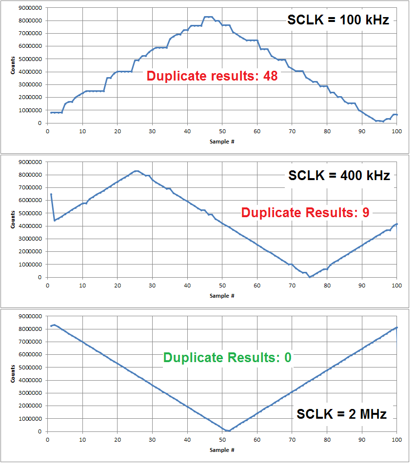
    The output results varied significantly with the SCLK frequency. Here my results for three SCLK frequencies:

    I'm working with the designer to try uncover the underlying cause for this behavior, but for the meantime I know that increasing the SCLK frequency appears to resolve the issue.

    Best Regards,
    Chris

  • Hi Chris,

    Do you see the same behavior using the read continuous mode?

    For the isolator 2MHz is pushing it.  I can probably go up to ~500KHz. There is about a 1uS round-trip propagation from non-isolated SCK to non-isolate SDI (MISO). 

    Mike

  • Hi Mike,

    I've been testing out many SPI sequences today. So far, I do NOT see the duplicate output behavior while operating in read data continuous (RDATAC) mode, when using the 100 kHz SCLK. You should be fine using the slower SCLK speed in RDATAC mode!

    However, while the RDATAC mode does not appear to have the duplicate output behavior, it does require that you monitor the /DRDY pin (not the DRDY register bit). I don't know if you're currently passing the /DRDY signal across the isolation barrier, but you'll most likely need it to use the RDATAC mode...

    Many of my test sequences have been attempting to find a way to interrupt RDATAC mode (going into SDATAC mode) to poll the DRDY register bit (to try to remove the need for passing the /DRDY signal through the isolation). In some cases, I can do this without triggering duplicate output results (by inserting certain delays into the code); however, currently I don't think this method is reliable enough to recommend. The best results have been to keep the ADS1259 in RDATAC mode.

    Note: If you operate in RDATAC mode AND pulse convert mode, you can send the START command without having to go into SDATAC mode. Therefore, the SDATAC command should only be needed to read or write to the registers.

    Best Regards,
    Chris
  • Mike,

    If you use the following procedure, it will allow for the 100 kHz SCLK frequency and for polling the DRDY register bit (so that the /DRDY signal does not need to pass through isolation:

    	// Set START pin low
    	// Send SDATAC command to perform WREG operation
    	// Configure ADS1259 for PULSE conversion mode {0x25,0x80,0x90,0x00,0x00,0x00,0x00,0x00,0x40}
    
    	// LOOP
    	{
    		// Send RDATAC command
    		// Send START command
    		// Delay ~105ms (must wait at least 40ns after /DRDY goes low and account for some clock tolerance - see Table 9) 
    		// Send SDATAC command to perform RREG operation
    		// Read CONFIG2 register with RREG command
    		// Check status of DRDY bit
    		// IF (DRDY == 1)
    			// Conversion timeout error
    		// ELSE IF (DRDY == 0)
    			// Read data with RDATA command
    	}

    This procedure gives you control of when conversions start; and by waiting until the conversion is sure to have finished, you will not violate the tSCDR or tDRSC timing requirements in Table 18.

    Let me know if this procedure will work for you!

    Best Regards,
    Chris

  • Hi Chris,


    We finally got all this stuff working!   I just wanted to get to you feedback.

    One follow up question.  We have noticed out of 32 channels (32 ADS1259 parts) that two have what appear to have more gain drift than all the others.   We have not performed any internal calibration within the ADS1259.  Could,  not calibrating ADS1259 contribute to more gain drift?  The target is in a temperature chamber between -50C to +90C and the voltage source is outside the temperature chamber. 

    For the channels with excessive gain drift, the resulting output counts from the A/D seem to drop as the temperature falls beginning around +50C and then linearly falling.  From about +50C to -90C it drops by   179200 counts out of 8304723  (average)  or about ~2% which is excessive (i.e. equivalent to a 50mV variation at the A/D input).  Other ADS1259 channels the total drift is no worse than 0.1% and typically better.  We have an LTC2055 driving the ADS1259 (this text does not explain the full story, but it is a starting point).  Any thoughts of where to look or thoughts about how to troubleshoot from ADS1259 perspective?

    Since the worse gain drift is at -50C we measured the reference voltage at a couple of channels (comparing) including the one with excessive gain drift and they are all within 1mV of each other.


    Thank you!

  • Hi Mike,

    Are you really testing below -50 C, or was that a typo?
    The ADS1259 is only rated for temperatures between -40 and +125 C. Going outside of this range will certainly degrade the device performance.

    A note about measuring gain error drift measurements...
    Often times gain error drift is calculated by sweeping the device over the entire temperate range and then subtracting the MAX and MIN gain errors by the whole temperature range (box method). This provides an "average" gain error drift over the entire temperature range; however if your looked at a smaller subset of temperatures, you might observe a larger or smaller rate of change in the gain error than what is given by the specified "average" gain error drift.

    Regarding calibration,
    It's unlikely that a single-point gain error calibration will have any effect on the gain error drift. A single-point calibration just reduces the initial gain error of the device. The best way to reduce the gain error drift is to re-calibration often (though not always practical). A more likely implementation is to calibrate the device at multiple temperatures to limit the gain error drift somewhat, but this adds complexity to the design and requires that the production line has this capability (and can afford the additional time) to perform a multi-point temperature calibration.

    Best Regards,
    Chris
  • Hi Chris,

    Yes, we test down to -50C, we just want to see what happens after -40C. But, good point. Yes from -40C to -50C that would contribute about 20% to the overall gain drift. OK, that makes the drift a bit smaller.

    Do you mean that below -40C that the ADS1259 could be damaged?

    Do you have any advice, from ADS1259 perspective, where to look for gain drift related problems? Or what things could contribute to that? Seems like the voltage reference dominates in the gain drift, but could there be other things?

    Thank you for your help!
    Mike
  • Hi Mike,

    Anything can happen beyond the absolute maximum ratings, but usually there is some additional tolerance built into device to avoid quality issues. ...You might be interested in the following blog post that discusses what happens beyond the abs. max ratings when exceeding an op amp's supply range; it covers a different issue, but in general, the same principles apply to any case when a device is operated outside of its guaranteed datasheet specifications:

    For the ADS1259, I think you're fairly safe going to -50 C. I looked up some information on this device and found that we had ran some test downs to -55 C. I would be more concerned if you cycled the device temperature repetitively because over time this could cause mechanical strain, eventually leading to a failure.

    Regarding gain error drift, certainly the voltage reference is a major contributor to gain error and gain error drift. Likely you'll see the best performance around room temperature and increased drift around the temperature extremes. Additionally, if you use large filtering resistors for the input or reference pins of the ADC you may see higher than expected gain error drift, as the input bias currents on these pins will drift over temperature. I would strongly discourage using filtering resistors larger than 10 kOhm (even though large series resistors are an easy way of protecting the device against over-voltage conditions), the smaller the better when it comes to bias current offset and gain error (and their respective drift) contributions.

    Best Regards,
    Chris