This thread has been locked.

If you have a related question, please click the "Ask a related question" button in the top right corner. The newly created question will be automatically linked to this question.

ADS1299 ADC reading

Other Parts Discussed in Thread: ADS1299

Hi,

We are using three ADS1299 chips in daisy mode and fed sine wave from signal generator to one the input that is +ve fed to the INP and -ve fed to the INN.

My gain is 24 and i am using internal reference but i am facing two problems.

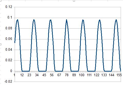
1)I fed a sine wave to the input but in my out put there is no negative peak .

2) I fed in put voltage is 4.48Vpp and i got output around +184mV.

I checked in the ADS1299 EVM also the out put is same.

  • Hey Manu,

    You will need to find an actively driven voltage for both the signal generator ground and the negative input to the device. The inputs to the ADS1299 are CMOS gates and so in your present setup, the ground connection for the signal generator is floating with respect to the board supplies. My recommendation would be to use the board ground if in a bipolar supply configuration or the output of the bias amplifier when not configured in BIAS_SENS if you are using unipolar supplies.

    Regards,
    Brian Pisani
  • Dear Brian,

    Thank you for your reply.

    But still i am confusing in some concept because my gain i set as 24 and i fed 2.32Vpp to the ADS1299 input.

    Here max input to the ADC is Vref/gain that is in my case it is 4.5/24=187.5mV. So any voltage more than 187.5mV when i applied to the ADS1299 should saturate.

    But when i applied 2.32Vpp at 24 gain i am getting output is 96mV how it is possible ? and i saw my out got saturated at 5.12Vpp only that time my out is 187.5mV.

    I repeated the same experiment in ADS1299 EVM also the output was same.

    Input to the ADS1299EVM and my board 

    Output of ads1299 EVM

    Output from my board plotted in Excel.

  • Hey Manu,

    Strange things tend to happen when there is no actively driven common mode. My guess is that once that is sorted out, things will start to look a lot better.

    Brian

  • Hey Brian

    I have a doubt regarding bias drive connection for multiple devices.

    We connected 3 ads1299 chip in the daisy chain configuration and I didn't connect 3 chips BIASINV pins together that mentioned in the datasheet (page no:53).

    so is this make any issue?

    I took frontend chip biasout to outside and all others are floated.

  • Hey Manu,

    The only reason you'd want to connect them is so that each channel can provide feedback to the amplifier which will actually be driving the bias electrode. Are you using the BIAS_SENS functionality? If not then you don't need to daisy chain them like in the datasheet.

    Regards,
    Brian