


Other Parts Discussed in Thread: AFE4400
Hello,
I am using the AFE4400 with the SFH7050 sensor and a PIC micro-controller but I do not get a measure sufficiently stable and good.
I configure the registers of the clock edge mapping as it described on the page 31 of the datasheet of the AFE4400.
I configured the other registers as follows:
REG CONTROL1: 0x0107
REG TIAGAIN: 0x000
REG TIA_AMB_GAIN: 0xA0085
REG LEDCNTRL: 0x11010
REG CONTROL2: 0x20100
REG CONTROL0: 0x001
Next I read the LED1VAL register (IR LED) whenever the ADC_RDY pin goes high level. I attach an imagen of this signal.

I use the filter function to detect the pulses. I find this function in the "PulseOx_HRM" document of the TI_HEALTH_HUB sources. I attach an imagen of the filter signal. I have noted that there are a heart pulse when this signal change negative to positive and then I calculate the heart rate with the time between pulses. The calculated frequency is not constant and is inaccurate.

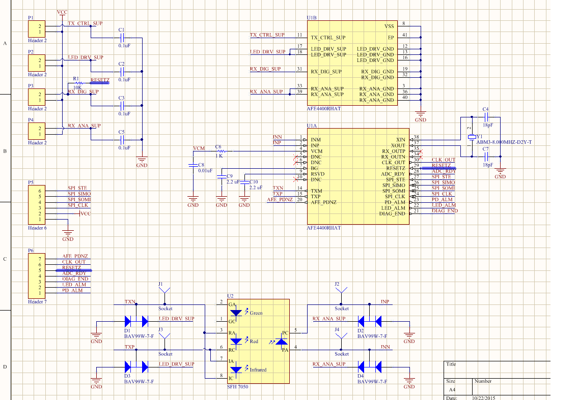
I attach an imagen of the schematic of the PCB board that I have made.
Best Regards,
