This thread has been locked.

If you have a related question, please click the "Ask a related question" button in the top right corner. The newly created question will be automatically linked to this question.

ADS131 Apparently Latching to AVDD?

We are using the ADS131 reference board and are seeing some odd behaviour.


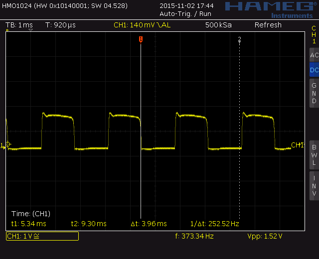
Input is a 400 Hz reference signal. The observed trace in the EVM software shows the signal railing to 2.4 V.

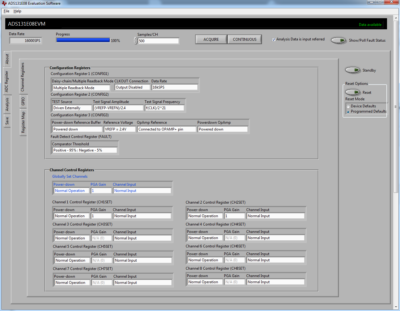
I've attached screen shots of the captured data from the EVM software, the settings of the EVM software, and a scope capture of the actual input signal, captured at the dev board terminals.


Any ideas on what we're doing wrong here?
  • Mr Zarikoff -
    How are you connecting the input signal to the EVM? Can you provide more details?
    A couple common issues that may be occuring:
    1. Are you driving a single-ended signal to one of the signals (perhaps the + input) and then floating the negative input? The ADC input signal is differential so you will need to bias the negative input of the input signal also.
    2. Make sure the common mode voltage of the signal is within the limits of the device.
  • Hi Greg,

    Thanks for the reply.

    1. The negative input is attached to the signal ground, not floating. The MMB0 board ground is also connected to the signal ground.
    2. The common mode voltage in this case would be around 0.75 V.

    Brad.
  • Hello Mr Zarikoff -
    A quick observation from your settings screenshot? Are you setting the gain to N/A(0) or is this the software sync doing this? This is an invalid setting, so make sure you aren't selecting this gain.
  • Hi Greg,


    The N/A(0) is set on software sync, but you can see from the screenshot that channels 1 and 2 have PGA set to 1. I presume there is no requirement to set all PGA's valid, but I can report that I have tried to do this to no avail.

    I will add that the tool appears to randomly set registers values after the MMB0 is booted and loaded with FW. This is why I sent along a snapshot of the configuration, in case there was another register set that may result in a bad value.


    One other question: what is the time scale of the x-axis? Is it samples? In which case running at 16 ksps would mean the signal frequency is = 16 ksps/85 samples = 188 Hz. This is off by a factor of 2... is the sampling rate actually the sampling bandwidth (ie. 16 ksps is actually 32 ksps?)? I am going to try with a signal generator next.