This thread has been locked.

If you have a related question, please click the "Ask a related question" button in the top right corner. The newly created question will be automatically linked to this question.

DAC3482EVM using external DACCLK

Other Parts Discussed in Thread: LMK04808, CDCE62005, DAC3482

Hi,

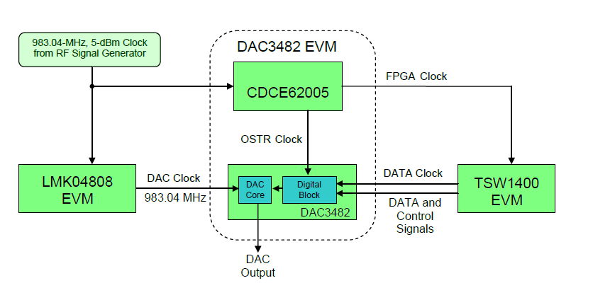
I am trying to setup CW signal of 30MHz using TSW1400 and DAC3482EVM using external DACCLK supplied by LMK04808 EVM but could not get signal out properly, I got FIFO collision alarms. Setup block diagram picture provided below:

DAC3482EVM is modified with the following:

- R154 and R155 is removed

-R124 and R125 jumper is installed

-LMK04808 EVM is programed with 983.04MHz LVPECL 1600mVpp. CLKout0/0* wired to J23 and J22 of DAC3482EVM

-DACCLK=983.04MHz supplied by LMK04808

-FPGACLK=61.44MHz supplied by SigGen CDCE62005 Y3=983.04MHz/16

-OSTR=983.04MHz/64

-Interpolation 4X

-TSW1400EVM data rate set to 245.76MHz


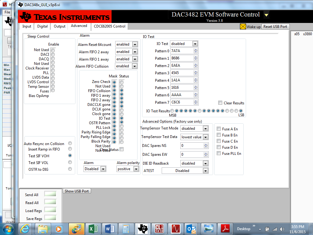
What might be wrong here and how can I correct it? The FIFO Alarm GUI picture shown below

Thanks!


  • Hi, Florence:

    1> I have checked your clock figuration. And I haven't find questions. I think you are right in clock configuration.
    2> Have you ever tried this configuration with DACCLK provided by CDCE62005 rather than external clock generator(LMK). I think you should validate this test first.
    3> The alarm 'DACCLK gone' appears. So I wonder the DACCLK differential inputs may have some problem:
    a) The differential pair of DACCLK should be matched and closely transmitted.
    b) The DACCLK should be provided first then load DAC configure data.
    c) Try to back off LVPECL level to LVPECL(700mVpp) or LVPECL(1200mVpp) to see whether it helps. I am afraid of the DACCLK swing because the minimum single ended swing is -0.4V with a 0.2V common mode voltage.
    4> Regarding the FIFO collision alarm, try to vary FIFO deep to see whether it helps.

    Thanks a lot!
    Yarn,
  • Yarn,

    Thank you very much for looking into this!

    1) I have tried with DACCLK from CDCE62005, everything works fine

    2) Found the issue is DACCLK coming from LMK04808 does not look correct on the DAC3482EVM , it appear to be impedance issues of the transmission line, I don't fully understand:


    a) Image 1 shows setup LMK04808 output to LVPECL 2000mV, probe right at the LMK04808 EVM CLKout0 SMA output connector. Correct clk frequency is observed= 983.04MHz at 60mV pk-pk, this output is AC coupled signal with DC bias =0V

    b)Image 2 shows probe this DACCLK signal right at the J22 connector at the DAC3482 EVM. Noticed the CLK signal is almost gone, instead the tiny clk signal is riding on some slower AC signal!

    c)Image 3 shows probe the DAC3482 EVM CDCE62005 DACCLK signal output, looks to me the bias DC voltage is 1.9V, I use AC couple on the probe.

    d)Image 4 shows my eval board setup and cable (SMA to SMB) from LMK04808 to DAC3482 EVM

    e) If I disconnect the SMA to SMB cable, then CLK signal on SMB side looks correct. It looks like impedance loading issue between the two eval board makes the CLK signal to be distorted when cables are connected.

    Question:

    1) DAC3482 DACCLK input looks like a AC coupled LVDS termination, is this OK with LMK04808EVM output impedence and signal LVPECL setting?

    2) My cable is 36inches long SMA to SMB 50 ohm cable, what cable would you recommend to connect these two EVM?

  • Yarn,

    Found out my cable is an issue, it is not making the pin contact! I thought the connector J22 and J23 is SMB, but I guess it is not making proper pin to socked contact with my SMB cables. What connector is it and what cables do you recommend? Thanks!

    Florence

  • Hi, Florence:

    I think connector J22 and J23 is SMP. I have tried with SMP female to SMA male cable, and it connects well.
    The cable I used is Rosnenberger 71w-19k1-32s1-00914 just for your information.

    Thanks a lot!
    Yarn.