This thread has been locked.

If you have a related question, please click the "Ask a related question" button in the top right corner. The newly created question will be automatically linked to this question.

DAC7750IPWP, 4-20mA LOOP driver erratic behavior

Other Parts Discussed in Thread: DAC7750

DAC7750IPWP issues :


1 -> 1.2V present on AVDD even if AVDD is not powered:

We observed a 1,2V on both DAC7750 AVDD when we have only the 3V3 rail powered (DAC7750 DVDD). Under this condition, the devices POR wont works as it should work only with AVDD < 1V (datasheet section 7.3.8). Is this a normal behavior of the DVDD/AVDD rails?


2 -> ALARM signal level when AVDD is not present:

The 2 DAC7750 ALARM signals are plugged in parallel to form a wired-AND function (as stated in section 7.3.9 of the datasheet). When the AVDD power is removed from 1 or from the 2 of the DAC7750, the ALARM signal voltage level varies from 2V to 2.4V. The ALARM terminal should be an open-drain output terminal (datasheet p.5), so the voltage level should stay at 3.3V from the pull-up. This behavior is problematic because this voltage level goes under the high logic level threshold of our MCU. Also, in our application, we can have none, one or two current loop powered. Is this a normal behavior of the Alarm terminal?


3 -> Output short circuit protection:

We would like to know if there is a simple way to protect the output current against a short-circuit condition (receiver or defective cable) in operation? Our tests shown that the DAC7750 is too slow to limit the current in this situation and its results in a blown chip (short between AVDD and GND).

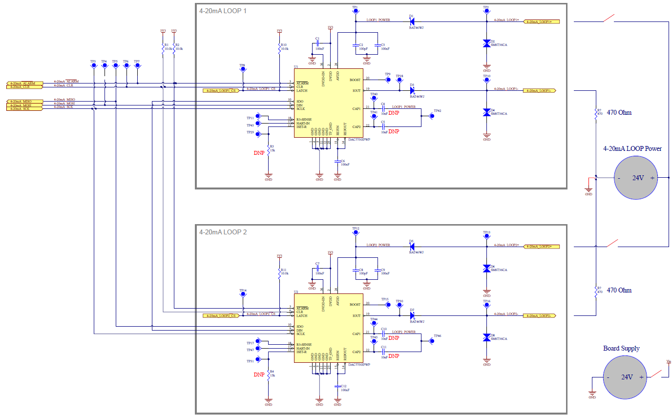
Here is our circuit and test setup:

  • Howdy user,

    Thank you for the post. I am currently looking into this post and have forwarded these questions to the designers. I will update this post as I receive information.

    Best Regards,
    Matt
  • Hi User,

    Apologies for the delay.

    user4465321 said:
    1 -> 1.2V present on AVDD even if AVDD is not powered:

    The designer confirmed that there is an ESD diode that links DVDD to AVDD. This is normal behavior. You should be able to power-on AVDD without any adverse effects. The device includes a POR circuit that takes care of any discrepancies when powering on the device with out of sequence supplies.

    user4465321 said:
    -> ALARM signal level when AVDD is not present:

    This is a bit strange. Is only AVDD removed? We suspect that if DVDD is still being supplied, due to the effect of the back-powering above, the ALARM pin might be powering the transistor on.

    Can you verify what happens when you also remove DVDD?

    user4465321 said:
    3 -> Output short circuit protection:

    We had another customer report a similar issue with an Open to Short test on the Iout pin with a 100 nF cap load. We have yet to be able to replicate the issue with no capacitor. Where are you shorting the output to GND? At the TP16 terminal? The diodes you have in place would aid the circuit.

    We are still investigating this issue, but the current work around is to add a 15 Ω resistor in series with Iout. This seems to limit the current enough to protect the device.

    Please let me know if I can clarify anything for you.

  • user4465321 said:
    3 -> Output short circuit protection:

    In addition to my previous post. I should mention that we have never seen this issue with a 24 V supply. We have only been able to replicate it with supplies > 30 V.

    Can you confirm that the supply used in the circuit is 24 V, as outline by the schematic?

  • 1 -> 1.2V present on AVDD even if AVDD is not powered:

    The issue with this condition is if we have only the AVDD of LOOP2 powered, the data are not transfered through DAC1 to DAC2. If the AVDD of LOOP1 is powered at the beginning and removed after the first command, the Daisy Chain communication is still functional.

    In our application, the 2 DAC is not always used at the same time.

    2 -> ALARM signal level when AVDD is not present:

    Only AVDD is removed, the 3V3 at DVDD pin is provided by the logic power of the board, I can't remove DVDD of any DAC during a normal use. The ALARM line is pulled up by the 10k resistor to 3V3 logic and the internal MOSFET seem not right activated when we lost AVDD. This MOSFET is activated by the AVDD or the DVDD supply?

    3 -> Output short circuit protection:

    The short circuit is occuring at load's terminals (between Iout and GND). I will try to place the 15Ohm series resistor to limit the short circuit current.

  • I confirm that the LOOP power is 24V when the short circuit issue is occurring.
  • I have tested the 15 Ohm series resistor and now we are able to support all shot circuit conditions.
    Short circuit on starting @ 24V and 32V LOOP power
    Short circuit during operation @ 24V and 32V LOOP power
    Operation, open loop to short circuit @ 24V and 32V LOOP power
  • Thank you for giving us this update. As I mentioned earlier, we have yet to see failures at a voltage lower than 30 V. I will inform the designers of this report.
  • Thank you for the follow-up.

    You have any explanation why the DAC1 doesn't transfer the data to the DAC2 when AVDD of DAC1 isn't present?
    As I mentioned earlier, the 2 DAC is not always used in all applications of the product.

    And you have an explanation for the Alarm signal goes wrong when AVDD of one or other DAC aren't present? The internal Open/Drain MOSFET is activated by DVDD or AVDD supply?
  • user4465321 said:
    You have any explanation why the DAC1 doesn't transfer the data to the DAC2 when AVDD of DAC1 isn't present?
    As I mentioned earlier, the 2 DAC is not always used in all applications of the product.

    I had misunderstood your query, I am checking with the designers to see if the digital interface operates normally without AVDD present. I do know that during power on, both DVDD and AVDD are used to set the default register settings, so I suspect that there might be some corruption during the power-on of the digital interface.

    user4465321 said:
    And you have an explanation for the Alarm signal goes wrong when AVDD of one or other DAC aren't present? The internal Open/Drain MOSFET is activated by DVDD or AVDD supply?

    It is activated by AVDD, therefore the back-powering of AVDD will cause problems.

  • Eugenio Mejia said:
    user4465321
    You have any explanation why the DAC1 doesn't transfer the data to the DAC2 when AVDD of DAC1 isn't present?
    As I mentioned earlier, the 2 DAC is not always used in all applications of the product.

    Following up on this question.

    The designer says that while the digital block does not depend on AVDD, it depends on the POR block which due to the back-powering of AVDD may flicker causing the digital block to reset intermittently. The designers do not recommend attempting to use the device in this manner.

    Going back to the over current issue. Would it be possible for you to send us some of there devices that failed at 24 V? We would like to perform a failure analysis on a couple of these devices to further understand the problem at hand.

  • Sorry, we threw all the broken components.