This thread has been locked.

If you have a related question, please click the "Ask a related question" button in the top right corner. The newly created question will be automatically linked to this question.

ADS1148 doesnt return expected result

Other Parts Discussed in Thread: ADS1148

Hi there

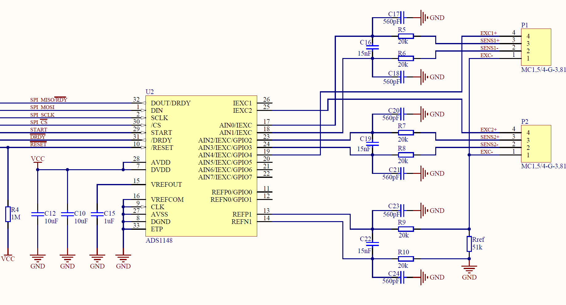
We are using the ADS1148 for temperature-measurement with an PT1000 RTD in 4-Wire application. Anyhow the result of the AD conversion is not the one that is expected when the PGA-gain is set to 32. When The gain is set to 1 the result of the conversuion is right. Here is the configuration of the ADS1148:

RTD:     approx. 1.1kOhms at room temperature

Ref:       Internal voltage Reference 2.048V

PGA:     32

I_exc:    50uA (Output at AIN5)

IN:          AIN_P = AIN6 / AIN_N = AIN7

DOR:     10SPS

The register values for this configuration are:

MUX0 = 0x37

VBIAS = 0x00

MUX1 = 0x30

SYS0  = 0x51

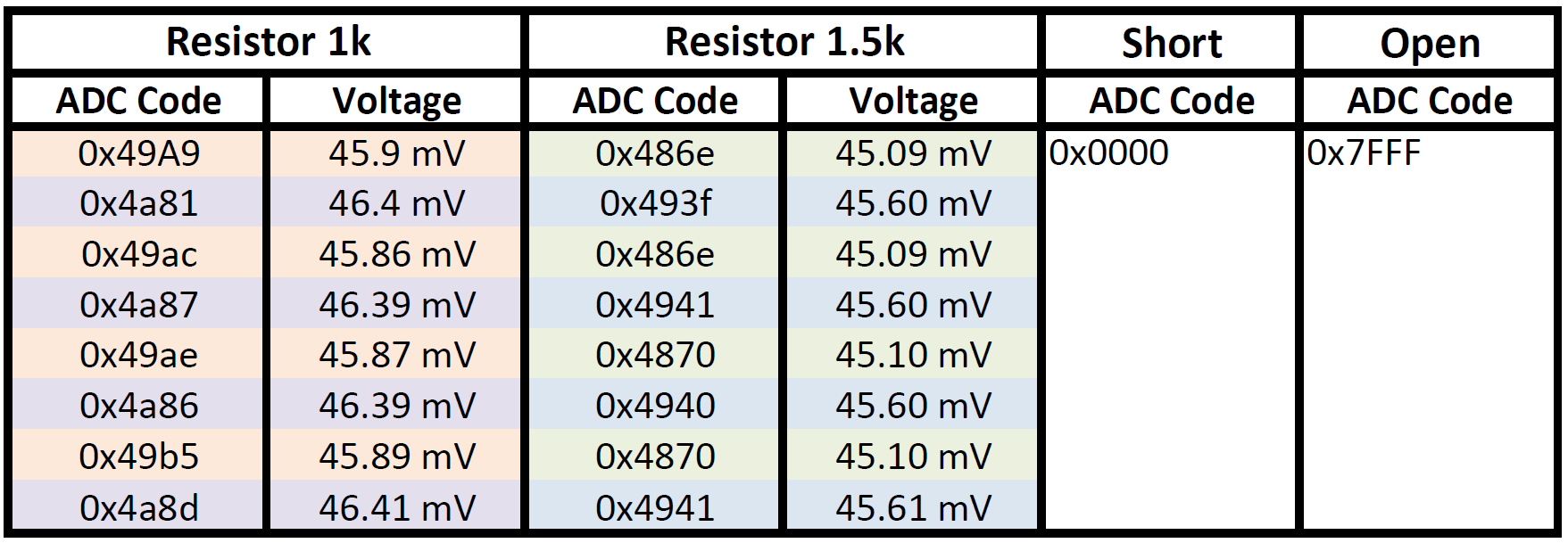
With this configuration we would expect a result of approximately 0x63FF for an analog differential input voltage of approximately 55mV (50uA*1.1kOhms) . The ADS1148 returns a value of 0x067A.


With the PGA set to 1 the result of the ADS1148 is similiar to the expected result (around 0x0360).


DO you have any idea what the cause of the problem could be?

Stefan

  • Stefan,


    I'd need to see the schematic to be sure, but at first guess, I think that you are outside the common-mode input range of the ADC. Do you have one end of the RTD tied to ground (or AVSS)? The front-end PGA gain is set up like an instrumentation amplifier. Because of this, you have to makes sure that the input is within the common-mode input of the PGA. In gain, this becomes more difficult because the output of the PGA needs to stay within the operating range of the op-amps as well.

    It's is listed in the Electrical Characteristics but the common-mode input range is AVSS+0.1V+((VIN)(GAIN)/2) on the low side to AVDD-0.1V-((VIN)(GAIN))/2 on the high side.

    I'd also like to point out that the way you have your RTD measurement set up is rather inaccurate. The IDAC currents have an absolute accuracy of 6% max. So multiplying your 50uA by the RTD value will already have a 6% max error associated with it.

    The best way to make a measurement with the RTD is to use a ratiometric measurement. Use a known precision resistor as the reference resistor and then send the IDAC current through the RTD through the reference resistor, connecting the reference resistor to REF0 (or REF1). When you make the measurement, the output code divided by the full-scale is the same ratio of the RTD to the reference resistor. This measurement is much more exact.

    For an example of how this is done, look at this application note: www.ti.com/.../sbaa201.pdf. It explains how to make ratiometric measurements with RTDs.


    Joseph Wu
  • Joseph,

    I actually tied one of the four rtd pins to avss and used the internal vref. With using an external resitor to generate vref, the problem is gone. thank you for your quick reply!

    Thanks
    Stefan
  • Hi Joseph,

    we have again troubles with the result od the conversion of the adc. After it worked properly on the evaluation-board, we implemented the ads1148 on our pcb. The depending schematic is shown in the picture below. We are using ratiometric-setup to measure a PT1000-Sensor which is connected to connector P1. The SPI-communication works fine (write register and read it again). Now te problem is that the ADS1148 gives a strange  result of around 0x49A9 with a 1k-resistor as PT1000-simulator. We would expect a voltage of 50mV with this 1k-resistor and a exc-current of 50uA.

    Below is the code of one measurement. Since we need a low power operation, we set the ADS1148 always back to sleep by clearing the START-pin.

    		// Reset ADS1148
    		nrf_gpio_pin_clear(ADC_RESET_PIN);
    		nrf_delay_us(6);		// Pulslength
    		nrf_gpio_pin_set(ADC_RESET_PIN);
    		nrf_delay_us(600);	// Waittime after reset
    	
    		// Wake up ADS1148
    		nrf_gpio_pin_set(ADC_START_PIN);
    	
    		// Configure Measurement
    		m_transfer_completed=false;
    		m_tx_data_spi[0] = 0x40;						// Start Block write at MUX0 register
    		m_tx_data_spi[1] = 0x03;						// Index of last Byte in block
    		m_tx_data_spi[2] = 0x01;						// MUX0 Register Config (AIN0/AIN1)
    		m_tx_data_spi[3] = 0x00;						// VBIAS Register Config 0V
    		m_tx_data_spi[4] = 0x68;						// MUX1 Register Config (Internal Reference On)				
    		m_tx_data_spi[5] = 0x52;						// SYS0 Register Config (PGA 32, 20SPS)
    		spi_send_recv(SPI_MASTER_0,m_tx_data_spi,6,m_rx_data_spi,0);
    		while(m_transfer_completed==false);
    	
    		m_transfer_completed=false;
    		m_tx_data_spi[0] = 0x4A;
    		m_tx_data_spi[1] = 0x01;
    		m_tx_data_spi[2] = 0x01;						// IDAC0 50uA
    		m_tx_data_spi[3] = 0x4F;						// IDAC1 I1DIR = AIN5
    		spi_send_recv(SPI_MASTER_0,m_tx_data_spi,4,m_rx_data_spi,0);
    		while(m_transfer_completed==false);
    		
    		//Self Offset Calibration
    		m_transfer_completed=false;
    		m_tx_data_spi[0] = 0x62;
    		spi_send_recv(SPI_MASTER_0,m_tx_data_spi,4,m_rx_data_spi,0);
    		while(m_transfer_completed==false);
    		nrf_delay_us(20); 									// Wait until calibration is done
    					
    		// Toggle Start Pin
    		nrf_gpio_pin_clear(ADC_START_PIN);
    		nrf_delay_us(10);
    		nrf_gpio_pin_set(ADC_START_PIN);
    
    		// Wait until ADC-Conversion is finished
    		while(nrf_gpio_pin_read(ADC_DRDY_PIN)==1);
    		
    		// Read ADC Data 
    		m_transfer_completed=false;
    		m_tx_data_spi[0] = 0xFF; 	// DUMMY-Byte
    		m_tx_data_spi[1] = 0xFF;	// DUMMY-Byte
    		spi_send_recv(SPI_MASTER_0,m_tx_data_spi,2,m_rx_data_spi,2);
    		while(m_transfer_completed==false);
    		
    		// Set ADS1148 to sleep
    		nrf_gpio_pin_clear(ADC_START_PIN);

    DO you have any idea what the cause of this problem could be?

    Thanks

    Steve

  • Steve,


    With a 50uA excitation current, you should see about 2.55V on the reference resistor, and as you mention 50mV on the 1k RTD simulator. With the resulting output data, you get 49A9h which translates to 18857d. Making all the calculations, accounting for a gain of 32, this reads approximately 917 Ohms (instead of 1k). So you're close to the right value, but you should be much closer.

    First, check to see that your resistances are correct. Your resistors should be precision resistors, since any errors in the resistance will be a gain error in the measurement. Second, I would measure back the voltages across the the 1k and 51k resistors. They should be 50mV and 2.55V. While they may not have the same exact values, they should have the same exact ratio. Use a precision multimeter so that you can get an accurate reading.

    Check to see if there's anything else connected to the board that might be causing a leakage current. The ratiometric measurement is dependent on making sure that the exact same current flows through the RTD and the reference resistor. Often TVS diodes are used on the inputs and the leakage from that can cause an error.

    Also, your input filtering resistors may be too high. With 20k resistors on the input, the analog input current may be creating a voltage that causes an additional error.

    I'd check those few things and post back the results.


    Joseph Wu
  • Hi Joseph,

    I did check these things you told me:

    • The resistance of the 1k-simulator is 985 ohms. The resistance of the 1.5k-simulator is 1493 ohms. The 51k-reference resistor has a tolerance 0.1%.
    • The voltagesof the 1k-rtd-simulator are 48mV (measurement) and 2.486V (reference) are in the correct ratio.
    • The voltagesof the 1.5k-rtd-simulator are 73mV (measurement) and 2.486V (reference) are in the correct ratio.
    • Voltage drop of the 20k-filter-resistor is under 1mV and should not be the cause of this problem.
    • There is nothing more connected to the to the board which could leak current of the exc-current.

    I did a measurement with a 1k-rtd-simulator and a 1.5k-rtd-simulator. In the table below are 8 samples shown. The measurement result of the 1.5k-simulator is completly wrong. Anyhow additionally there is a toggling in between codes with both the 1k and the 1.5k-resistors. I marked this with fill-colors in the table. Between this toggling values are big steps as you can see.

    After setting down the pga to 4, the adc-code for both rtd-simulators was correct.

    I got the feeling that the cause of my problem is the common-mode-input-range. I use a power-supply-voltage of 3.3V which is connected to DVDD and AVDD. DGND and AVSS is connected to 0V. What do you think ehat the cause of this problem could be.

    Steve


  • Steve,


    I had assumed that you were running with a 5V supply because you were using a reference that was near 2.5V. Generally, you would want to start with the reference value near mid-supply so that any measurement you make would be within the common-mode input range of the amplifier. The common-mode input range of the amplifier is given in the electrical characteristics table of the datasheet. In your case, I think you violate the upper range which is (AVDD-0.1V-(VINxGain)/2). By using a smaller gain, you fall back into operation. Gain of 4 works, while Gain of 32 doesn't.

    I'd also not that you are close to the upper compliance range of the IDAC current source. I don't think this is a big problem for you because the current gets reduced but the same current still runs through both the RTD and reference resistor.

    If you're using the 50 uA source, try reducing the reference resistor to 33k and re-run the experiment. This lowers the voltage across the reference resistor and puts the input very close to mid-supply so that the RTD measurement is in the common-mode input range.


    Joseph Wu
  • Hi Joseph

    I changed the reference-resistor to a 33k und the pga to 16 and it works perfectly now. Thank you for your fast and competent help!

    Steve