Because of the holidays, TI E2E™ design support forum responses will be delayed from Dec. 25 through Jan. 2. Thank you for your patience.

This thread has been locked.

If you have a related question, please click the "Ask a related question" button in the top right corner. The newly created question will be automatically linked to this question.

ADC128D818 Only reads 0 from Channel Reading Regs

Other Parts Discussed in Thread: INA2331

Hello, I cannot figure out why my digital output is always 0.

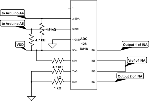
I am using an Arduino to read, but have verified readings/writings with a serial analyzer. Each output has a pull up resistor of 4.7k, A0 and A1 have pull down resistors only. My inputs are differential, where v in is between 0.5 and 1v, and come from the output and reference of an instrumentation amplifier (INA2331). First  tried using In0-In1 and In3-In2, then tried switching them to IN4-In5 and In7-In6. My code can read the registers, and all values written are read back correctly. This is what my code does:

SETUP:

1. wait until Busy status (adr xC)  reads 00

2. To Advanced Config Reg (adr xB) write 0x4, to set mode 2 and use internal Vref

3. To Conversion Reg (adr x7) write 0x1, for continuous conversion

4. to Channel Disable Reg (adr 0x8) write 0, to enable all channels

5. to Limits Reg (adr. 0x2E and 0x30) write 0x5, to set the limit of each my diff inputs to 5V

6. to Config Reg (adr0x0) write 0x0B, to clear interrupt, enable interrupts, Start conversion

At this point I read all the regs and confirm they were written properly. 

Loop:

1. read diff ch 3 (adr 0x22), read 2 bytes

2. read diff ch 4 (adr 0x23), read 2 bytes

3. read interrupt status reg (adr. 0x1) read 1 byte

4. delay 500ms and repeat

All readings are 0.

Can anyone see a problem in my setup? I tried changing the input channels, I even tried using a second chip, but I always get 0, not even the interrupts are helping. Any help is appreciated!

  • Hi Nathaly,

    When you are doing the ch3 and ch4 data reads are you setting the address as shown in Figure 31 in the datasheet? Also, do you have all the Acks and No Acks as shown in that figure?

    Mike
  • Hi Mike, 

      I am not using a repeat start, I am writing the register address and then sending a read command as in Fig 26 + 29, using a stop from master in between. Is this not valid? I don't know how to implement a repeated start, as I am using Arduino's Wire Library. Below is my serial stream and my code for reading. 

    Thanks!

    int myRead(byte regAddress, int numBytes)
    {
      int value =0;
      //Serial.println(" transmitting...");
      Wire.beginTransmission(MYADDRESS);
      Wire.write(regAddress);
      Wire.endTransmission();
      
      Wire.requestFrom(MYADDRESS, numBytes);
      
      while(!Wire.available() )
      {
        //wait till read is done
      };
     // Serial.println(" reading...");
      if (numBytes == 2)
      {
        value = Wire.read() << 8;
        value |= Wire.read();
      }
      else
      value = Wire.read();
      
      return value;
    }

  • Hi Nathaly,

    Sorry for the delay, I had to find parts and get your circuit put together so that I could try it out but I did find the problem.

    You are writing 0x0B (0000 1011) to the Config Reg (0x00). Bit 3, INT_Clear, when set to 1 stops the round robin monitoring loop. Set this register to 0x03 (0000 0011) or 0x01 (0000 0001) so that bit 3 = 0 and it should work .

    Mike
  • Hello Mike!

      Ive been busy with exams, but I am back and tried your suggestion. I only write (0x03) to the config register, but I am still getting readings of 0. I look into the status register a few times to get some clues, and I reset it at the very beginning just in case:

    -clear interrupt bit (write (0x08 to Addr00)

    -setup all my configurations

    -check interrupt status Addr01 ( --> get 0000 0000)

    -start conversion (write 0x03 to Addr0)

    -check interrupt status right after starting  (  --> get 1000 0000)

    -read all configuration registers  ( they all have what I intended)

    -read channels (--> get 0)

    -read interrupt status (--> get 1000 1111) meaning all my channels have gone below or above the limits of 0-5

       I am using the internal reference of 2.56V, so my analog input range should be between 0 and 2.56v correct? I am in differential mode, and IN1-IN0 is designed to be between 0-2.56, however IN1 on its own may go beyond that voltage. Can this have something to do with it? However, I am only using 4 pins (2 differential inputs) but I am getting limit interrupts for ALL, so not sure what could cause that.

    Thanks for looking into this, I appreciate your help!

  • UPDATE !
    The analog inputs to the ADC come from an instrumentation amplifier (INA2331) so I tried feeding the inputs directly from a voltage divider an input of 1.4 v ( according to datasheet that should result in a digital encoding of 2240). I got some readings! But the reading in decimal is -30800 and ALL interrupt bits are up. How could I read such a high number? the first byte read is MSB, correct?, are there 4 bits I should ignore to convert a 16 bit data into 12 bit?

    As soon as I use the amp outputs as ADC inputs,  I read 0. I am using the reference to the amplifier (~2.5v) as half a differential input, and the output of the amplifier as the other half. Is there a problem by using the same voltage line for amp-reference and adc-input?

  • Hi Nathaly,

    You are correct that VIN needs to be less than the reference. It actually needs to be 3LSB/2 less than the reference. See page 15 in the datasheet. The inputs can be above that but the difference needs to be less.
    The input shouldn't care where the voltage is coming from, it is only interested in what the voltage is. When you have the amplifier connected check that you have the expected voltages at the input pins of the ADC. Is there any noise or spikes on the voltages of the input pins?
    Are you using the internal reference? An experiment is that you could try using an external reference and set the reference voltage to 5V, just to see what kind of results that gives you

    Mike
  • So I figured that the value im reading is two bytes (==16 bits) but the ADC only outputs a 12 bit value. So I get my final value and mask it with 0FFF. The values are not crazy but they're way off what they should be [ d=(delta_Vin/Vref)*4096 ]

    I tried inputting a value straight from a power supply, with either internal or external 5v reference, and even on different channels. I am getting values but they still don't make sense.  So I used a sample arduino code for this adc from github and both my code and this code get the same value. This makes me thing theres something wrong with the circuit or chip.

    For example, if I am in single ended mode,  Input from power supply =1.8v,  

    with internal 2.56v reference, I should get 2880 encoding , but I get: 1488 (dec)

    with external 5v reference,  I should get 1474 encoding. but I get: 3216

    *If it makes a difference my interrupt register still reads 255, and ch7 temperature reading is between 1920 and 2048.

    Thanks, and happy holidays!

    ~Nathaly

  • Hi Nathaly,

    After reading the 2 bytes, discard the lower 4 bits and use the upper 12 bits for the data. For example if you read 1010 1010 1010 0000 you should discard the 4 lower bits that are 0000 and use 1010 1010 1010 as your twelve bits of data.

    Mike
  • Hoooorrraaaaay!!!!

     Hi Mike, Happy new year and all that jazz. Turns out I was misinterpreting the bits all along. I masked the lower 4 bits as you suggested and to keep the higher bits I divided the value by 16 and stored in an integer. 

    Thanks so much for your help, I got my circuit working now! :)

  • That's great to hear it is working.

    Mike