This thread has been locked.

If you have a related question, please click the "Ask a related question" button in the top right corner. The newly created question will be automatically linked to this question.

ADC10D1500RB, Question

Other Parts Discussed in Thread: WAVEVISION5, ADC10D1000, ADC10D1500

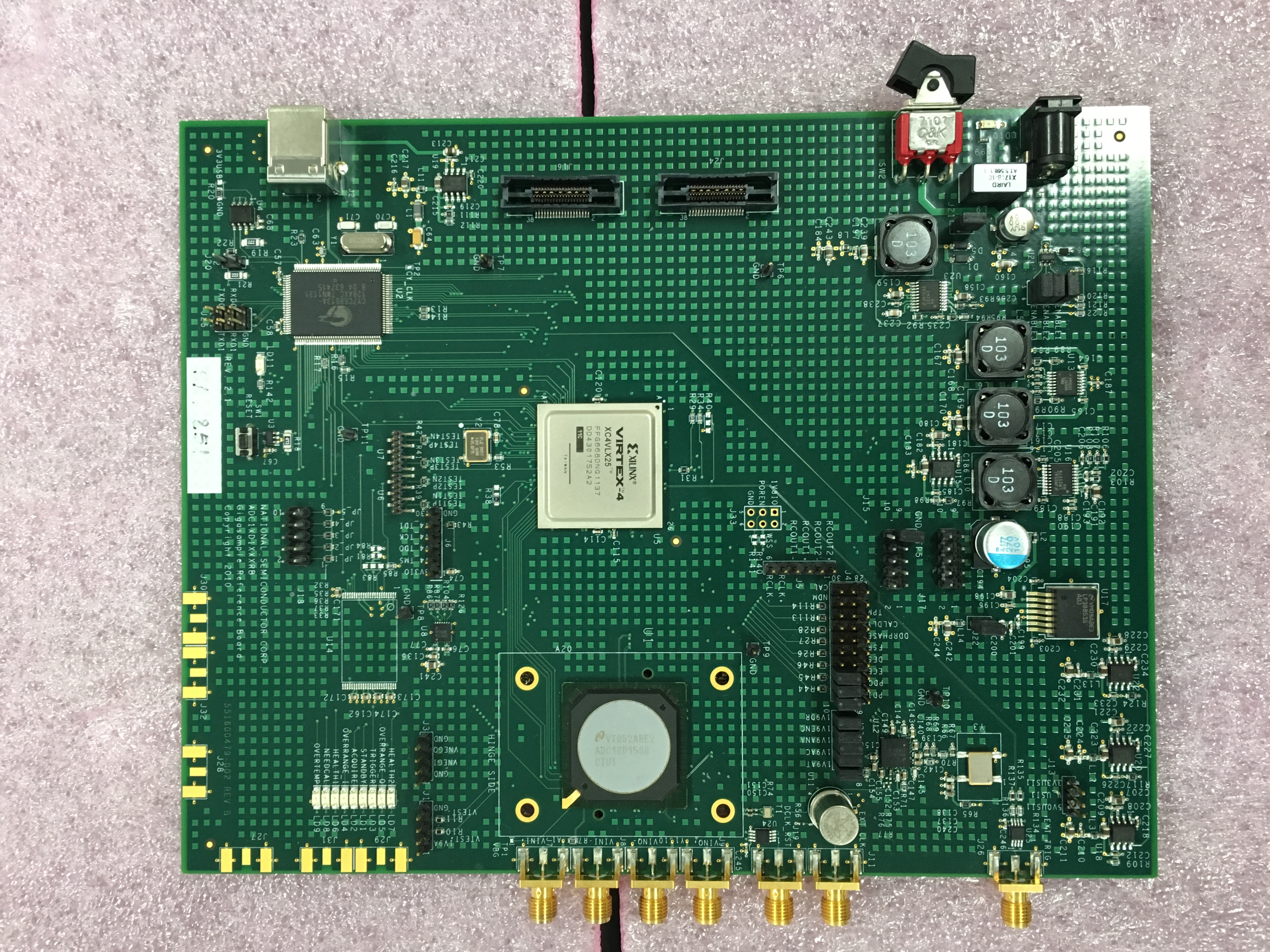
We are having some issues with the ADC10D1500RB.


We are trying to use the Ext. Mode while using the ADC10D1500RB.

We followed the instructions on the manual, and using WaveVision5, checked on the box for the H/W Trigger button.

Afterwards, we connected our H/W to the Ext. Trigger (J26) connector and sent a test signal.

However, we could not conclude whether the signal went through properly, due to no response on the Trigger LED on the board.


Our end goal is to be able to utilize board’s the External Trigger to control the board and use the oscilloscope mode on the board.


Please advise if there are any recommendations or steps to simplify this process.

  • Hi Jeong,

    External trigger mode is not supported on ADC10D1500RB is uses order firmware which does not support it.

    Regards,

    Neeraj Gill 

  • If this is the case, what is the purpose of the J26 Connector (Labeled as Ext. Trigger on the Manual) and is there a way to use an External Trigger with this ADC then?

  • Hi Dongjin

    When the ADC10D1500RB was initially released, the firmware/software combination did not support the hardware trigger function. When the WaveVision software added the trigger feature we started adding it into the firmware of newer boards, but the ADC10D1500RB did not get that update released.

    Can you please send a photo of the top of the board you have? I want to confirm which revision of board it is and then I will check to see if we do have a version of firmware that includes the trigger functionality for the board you have.

    Best regards,

    Jim B

  • Hi Jim.

    this picture is my ADC board.

  • Thanks Dongjin

    I'll do some checking to see if a version of firmware is available that supports external trigger on that board.

    Regards,

    Jim B

  • Thank you for your thoughtfulness.
  • Hi Dongjin

    Here are two different firmware files you can try:

    /cfs-file/__key/communityserver-discussions-components-files/73/8816.Older_5F00_Trigger_5F00_Fix.zip

    /cfs-file/__key/communityserver-discussions-components-files/73/4331.Newer_5F00_Trigger_5F00_Fix.zip

    They will be used in place of the original file which should be in this folder:

    C:\Program Files (x86)\National Semiconductor\WaveVision5\hardware\fpga_images

    The original file name will be "adc10d1000_xc4vlx25_adc10d1000rb.bit"

    Rename the original file to "adc10d1000_xc4vlx25_adc10d1000rb.bit.bak" and then copy the new file to be tested into that folder.

    Let me know if either of both of these work.

    Best regards,

    Jim B

  • Hi Jim

    I tried two different firmware files.

    but I think Ext.Trig is not work.

    check H/W Trigger, Input Signal is 1 V, 600 kHz, 100 ns, Trigger input signal is 5 kHz.

    I made it mistake?

  • Hi Dongjin

    The ADC10D1500RB hardware trigger is intended to synchronize the capture of data to an external trigger event. If the external trigger event is also synchronized to the input signal then this feature allows the capture of data to consistently occur with a particular timing relationship to the input signal.

    The hardware trigger function is not capable of repetitive capture of data at every trigger event. The trigger is used as follows:

    1. Hardware Trigger is enabled in the right panel of the GUI.
    2. Select single or continuous capture.
    3. Capture is initiated by clicking on the capture button at the top of the GUI.
    4. When the FPGA senses the trigger input going from low to high the storage of ADC data to memory is initiated. If single capture is selected only one capture event will occur. If continuous capture is selected the GUI will update as quickly as possible, and the captures will be synchronous to the trigger signal. Since the GUI update time is significantly longer than 200us (period of your 5 kHz trigger signal) it is not possible to update at that rate.

    If you are using the function in the sequence described above and if your signal and trigger generators are synchronized together, then the captured data should be consistently aligned in the sample window.

    Is this what you are doing, and is the alignment consistent?

    Best regards,

    Jim B

  • Hi Jim

    I want to use ADC to LIDAR application. (oscilloscope mode)


    how to change time scale?? (ex. 100ns/div, 100us/div ...) is it possible?

  • Hi Dongjin

    The ADC10D1500RB is provided to allow customers to evaluate the performance of the ADC10D1500 ADC device, so ensure it is suitable for their product before proceeding with design of their hardware.

    The board has the following limitations:

    1. sample rate range from 1000MSPS to 1500 MSPS with external clock or  fixed at 1500 MSPS with onboard clock
    2. maximum capture depth of 32k samples

    Given these limitations the board may not be suitable for a LIDAR application where you need a lower effective sample rate, or a much larger capture depth to provide the necessary duration (in time) of data.

    You might need to look at some more flexible digitizer products that other companies have created using the ADC10D1500 or similar devices. These commercial products will have more flexibility of sample rate and capture depth than our evaluation board has.

    Best regards,

    Jim B